


Fault tracing guide
Product Manual
11
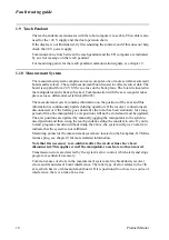
1.11 Disk Drive
The disk drive is controlled by the I/O computer via a flat cable. The power is supplied by
a separate cable.
Common types of error are read and write errors, generally caused by faulty diskettes. In
the event of a read and/or write error, format a new, high quality diskette in the robot and
check to see whether the error disappears. If the error is still present, the disk drive will
probably have to be replaced. However, check the flat cable first.
NB: Never use diskettes without a manufacturer’s mark. Unmarked, cheap diskettes can be
of very poor quality.
If the disk drive is completely dead, check the supply voltage connection to the disk drive
to see that it is +5 V, before replacing the drive.
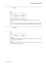
Measuring points are available on the backplane: X9 Maintenance plug, see chapter 9.
When replacing the disk drive, check that the strapping is set correctly on the unit. Compare
with the faulty drive being replaced.
1.12 Fuses
There is one automatic three-phase 20 A fuse that supplies the DC-link in the MOTORS
ON state, on the transformer. There is also a automatic three-phase 10 A fuse that supplies
the power supply unit. There are also two fuses for customer AC supplies, one 3.15 A and
one 6.3 A.
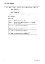
The backplane has four PTC resistance fuses:
- Serial measurement board 1
- Serial measurement board 2
- CAN2, manipulator I/O
- CAN3, external I/O
The fuses protect against 24 V short-circuits and return to the normal state when there is no
longer a risk of short-circuiting.
The panel unit has one PTC fuse to protect the motor on chains. An open fuse is indicated
on the teach pendant, see Status of the Panel unit, inputs and outputs, displayed on the teach
pendant side 6, 24 panel.
The cabling from customer 24 V supply is protected by a 2A fuse on terminal XT31 in the
upper compartment of the controller.
Note that the power supply unit DSQC 374 is provided with a short circuit energy limitation
which makes the fuse unnecessary.
Summary of Contents for IRB 6400R
Page 4: ...Description 20 Product Specification IRB 1400 M97A BaseWare OS 3 0 ...
Page 6: ...Introduction 2 Product Manual ...
Page 10: ...Introduction 6 Product Manual ...
Page 12: ...Product Specification IRB 6400R 2 Product Specification IRB 6400R M99 BaseWare OS 3 2 ...
Page 78: ...Accessories 68 Product Specification IRB 6400R M99 BaseWare OS 3 2 ...
Page 80: ...Product Specification RobotWare 2 Product Specification RobotWare for BaseWare OS 3 2 ...
Page 82: ...Introduction 4 Product Specification RobotWare for BaseWare OS 3 2 ...
Page 104: ...Interbus S 3 2 26 Product Specification RobotWare for BaseWare OS 3 2 ...
Page 110: ...I O Plus 3 2 32 Product Specification RobotWare for BaseWare OS 3 2 ...
Page 128: ...PalletWare 50 Product Specification RobotWare for BaseWare OS 3 2 ...
Page 132: ...Safety 2 Product Manual ...
Page 148: ...System Description CONTENTS Page 2 Product Manual ...
Page 158: ...Structure System Description 12 Product Manual ...
Page 160: ...Computer System System Description 14 Product Manual ...
Page 164: ...I O System System Description 18 Product Manual ...
Page 168: ...Safety System System Description 22 Product Manual ...
Page 170: ...External Axes System Description 24 Product Manual ...
Page 174: ...Installation and Commissioning CONTENTS Page 4 Product Manual IRB 6400R ...
Page 196: ...On Site Installation Installation and Commissioning 26 Product Manual IRB 6400R ...
Page 270: ...Installing the Control Program Installation and Commissioning 100 Product Manual IRB 6400R ...
Page 292: ...Maintenance CONTENTS Page 2 Product Manual IRB 6400R ...
Page 299: ...Maintenance Product Manual IRB 6400R 9 Figure 4 Lubricating gearbox axis 1 4 3 1 2 ...
Page 312: ...Troubleshooting Tools CONTENTS Page 2 Product Manual ...
Page 350: ...Troubleshooting Tools 40 Product Manual ...
Page 352: ...Fault tracing guide 2 Product Manual ...
Page 362: ...Fault tracing guide 12 Product Manual ...
Page 375: ...Motor units Repairs 12 Product Manual IRB 6400R ...
Page 401: ...Arm System Repairs 38 Product Manual IRB 6400R ...
Page 409: ...Cabling Repairs 46 Product Manual IRB 6400R ...
Page 441: ...Special Tools List Repairs 80 Product Manual IRB 6400R ...
Page 479: ...Part List and Spare Parts Product Manual IRB 6400R 38 ...
Page 480: ...Part List and Spare Parts Product Manual IRB 6400R 39 ...
Page 481: ...Part List and Spare Parts Product Manual IRB 6400R 40 ...


