


Safety
Product Manual
9
When the Hold-to-run control is active, the enabling device and the Hold-to-run button
on the teach pendant must be depressed in order to execute a program. When the button
is released, the axis (axes) movements stop and the robot remains in the MOTORS ON
mode.
Here is a detailed description of how to execute a program in Hold-to-run control:
• Activate the enabling device on the teach pendant.
• Choose execution mode using the function keys on the teach pendant:
- Start (continuous running of the program)
- FWD (one instruction forwards)
- BWD (one instruction backwards)
• Wait for the Hold-to-run alert box.
• Activate the Hold-to-run button on the teach pendant.
Now the program will run (with the chosen execution mode) as long as the Hold-to-
run button is pressed. Releasing the button stops program execution and activating the
button will start program execution again.
For FWD and BWD execution modes, the next instruction is run by releasing and
activating the Hold-to-run button.
It is possible to change execution mode when the Hold-to-run button is released and
then continue the program execution with the new execution mode, by just activating
the Hold-to-run button again, i.e. no alert box is shown.
If the program execution was stopped with the Stop button on the teach pendant, the
program execution will be continued by releasing and activating the Hold-to-run
button.
When the enabling device on the teach pendant is released, the sequence described
above must be repeated from the beginning.
7.6 General Mode Safeguarded Stop (GS) connection
The GS connection is provided for interlocking external safety devices, such as light
curtains, light beams or sensitive mats. The GS is active regardless of the position of
the operating mode selector.
When this connection is open the robot changes to the MOTORS OFF mode. To reset
to MOTORS ON mode, the device that initiated the safety stop must be interlocked in
accordance with applicable safety regulations. This is not normally done by resetting
the device itself.
Summary of Contents for IRB 6400R
Page 4: ...Description 20 Product Specification IRB 1400 M97A BaseWare OS 3 0 ...
Page 6: ...Introduction 2 Product Manual ...
Page 10: ...Introduction 6 Product Manual ...
Page 12: ...Product Specification IRB 6400R 2 Product Specification IRB 6400R M99 BaseWare OS 3 2 ...
Page 78: ...Accessories 68 Product Specification IRB 6400R M99 BaseWare OS 3 2 ...
Page 80: ...Product Specification RobotWare 2 Product Specification RobotWare for BaseWare OS 3 2 ...
Page 82: ...Introduction 4 Product Specification RobotWare for BaseWare OS 3 2 ...
Page 104: ...Interbus S 3 2 26 Product Specification RobotWare for BaseWare OS 3 2 ...
Page 110: ...I O Plus 3 2 32 Product Specification RobotWare for BaseWare OS 3 2 ...
Page 128: ...PalletWare 50 Product Specification RobotWare for BaseWare OS 3 2 ...
Page 132: ...Safety 2 Product Manual ...
Page 148: ...System Description CONTENTS Page 2 Product Manual ...
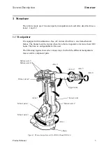
Page 158: ...Structure System Description 12 Product Manual ...
Page 160: ...Computer System System Description 14 Product Manual ...
Page 164: ...I O System System Description 18 Product Manual ...
Page 168: ...Safety System System Description 22 Product Manual ...
Page 170: ...External Axes System Description 24 Product Manual ...
Page 174: ...Installation and Commissioning CONTENTS Page 4 Product Manual IRB 6400R ...
Page 196: ...On Site Installation Installation and Commissioning 26 Product Manual IRB 6400R ...
Page 270: ...Installing the Control Program Installation and Commissioning 100 Product Manual IRB 6400R ...
Page 292: ...Maintenance CONTENTS Page 2 Product Manual IRB 6400R ...
Page 299: ...Maintenance Product Manual IRB 6400R 9 Figure 4 Lubricating gearbox axis 1 4 3 1 2 ...
Page 312: ...Troubleshooting Tools CONTENTS Page 2 Product Manual ...
Page 350: ...Troubleshooting Tools 40 Product Manual ...
Page 352: ...Fault tracing guide 2 Product Manual ...
Page 362: ...Fault tracing guide 12 Product Manual ...
Page 375: ...Motor units Repairs 12 Product Manual IRB 6400R ...
Page 401: ...Arm System Repairs 38 Product Manual IRB 6400R ...
Page 409: ...Cabling Repairs 46 Product Manual IRB 6400R ...
Page 441: ...Special Tools List Repairs 80 Product Manual IRB 6400R ...
Page 479: ...Part List and Spare Parts Product Manual IRB 6400R 38 ...
Page 480: ...Part List and Spare Parts Product Manual IRB 6400R 39 ...
Page 481: ...Part List and Spare Parts Product Manual IRB 6400R 40 ...


