


Fault tracing guide
10
Product Manual
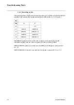
1.9 Teach Pendant
The teach pendant communicates with the robot computer via a cable. This cable is also
used for the +24 V supply and the dual operation chain.
If the display is not illuminated, try first adjusting the contrast, and if this does not help
check the 24 V power supply.
Communication errors between the teach pendant and the I/O computer are indicated
by an error message on the teach pendant.
For measuring points for the teach pendant communication signals, see chapter 9.
1.10 Measurement System
The measurement system comprises an axis computer, one or more serial measurement
boards and resolvers. The serial measurement board is used to collect resolver data. The
board is supplied from 24 V SYS via a fuse on the back plane. The board is located in
the manipulator and is battery-backed. Communication with the axis computer takes
place across a differential serial link (RS 485).
The measurement system contains information on the position of the axes and this
information is continuously updated during operation. If the resolver connections are
disconnected or if the battery goes dead after the robot has been stationary for a long
period of time, the manipulator’s axis positions will not be stored and must be updated.
The axis positions are updated by manually jogging the manipulator to the synchro-
nised position and then, using the teach pendant, setting the counters to zero. If you try
to start program execution without doing the above, the system will give an alarm to
indicate that the system is not calibrated.
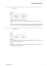
Measuring points for the measurement system are located on the backplane, X9 Main-
tenance plug, see chapter 9 for more detailed information.
Note that it is necessary to re-calibrate after the resolver lines have been
disconnected. This applies even if the manipulator axes have not been moved.
Transmission errors are detected by the system’s error control, which alerts and stops
program execution if necessary.
Common causes of errors in the measurement system are line breakdown, resolver
errors and measurement board interference. The latter type of error relates to the 7th
axis, which has its own measurement board. If it is positioned too close to a source of
interference, there is a risk of an error.
Summary of Contents for IRB 6400R
Page 4: ...Description 20 Product Specification IRB 1400 M97A BaseWare OS 3 0 ...
Page 6: ...Introduction 2 Product Manual ...
Page 10: ...Introduction 6 Product Manual ...
Page 12: ...Product Specification IRB 6400R 2 Product Specification IRB 6400R M99 BaseWare OS 3 2 ...
Page 78: ...Accessories 68 Product Specification IRB 6400R M99 BaseWare OS 3 2 ...
Page 80: ...Product Specification RobotWare 2 Product Specification RobotWare for BaseWare OS 3 2 ...
Page 82: ...Introduction 4 Product Specification RobotWare for BaseWare OS 3 2 ...
Page 104: ...Interbus S 3 2 26 Product Specification RobotWare for BaseWare OS 3 2 ...
Page 110: ...I O Plus 3 2 32 Product Specification RobotWare for BaseWare OS 3 2 ...
Page 128: ...PalletWare 50 Product Specification RobotWare for BaseWare OS 3 2 ...
Page 132: ...Safety 2 Product Manual ...
Page 148: ...System Description CONTENTS Page 2 Product Manual ...
Page 158: ...Structure System Description 12 Product Manual ...
Page 160: ...Computer System System Description 14 Product Manual ...
Page 164: ...I O System System Description 18 Product Manual ...
Page 168: ...Safety System System Description 22 Product Manual ...
Page 170: ...External Axes System Description 24 Product Manual ...
Page 174: ...Installation and Commissioning CONTENTS Page 4 Product Manual IRB 6400R ...
Page 196: ...On Site Installation Installation and Commissioning 26 Product Manual IRB 6400R ...
Page 270: ...Installing the Control Program Installation and Commissioning 100 Product Manual IRB 6400R ...
Page 292: ...Maintenance CONTENTS Page 2 Product Manual IRB 6400R ...
Page 299: ...Maintenance Product Manual IRB 6400R 9 Figure 4 Lubricating gearbox axis 1 4 3 1 2 ...
Page 312: ...Troubleshooting Tools CONTENTS Page 2 Product Manual ...
Page 350: ...Troubleshooting Tools 40 Product Manual ...
Page 352: ...Fault tracing guide 2 Product Manual ...
Page 362: ...Fault tracing guide 12 Product Manual ...
Page 375: ...Motor units Repairs 12 Product Manual IRB 6400R ...
Page 401: ...Arm System Repairs 38 Product Manual IRB 6400R ...
Page 409: ...Cabling Repairs 46 Product Manual IRB 6400R ...
Page 441: ...Special Tools List Repairs 80 Product Manual IRB 6400R ...
Page 479: ...Part List and Spare Parts Product Manual IRB 6400R 38 ...
Page 480: ...Part List and Spare Parts Product Manual IRB 6400R 39 ...
Page 481: ...Part List and Spare Parts Product Manual IRB 6400R 40 ...


