


On-Site Installation
Installation and Commissioning
28
Product Manual IRB 6400
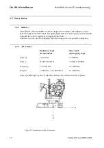
2.11 Mains power connection
Before starting to connect the mains, make sure that the other end of the cable is
disconnected from the line voltage.
The power supply can be connected either inside the cabinet, or to a optional socket on
the left-hand side of the cabinet or the lower section of the front. The cable connector
is supplied but not the cable. The mains supply cables and fuses should be dimensioned
in accordance with rated power and line voltage, see rating plate on the controller.
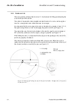
2.11.1 Connection to the mains switch
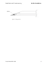
Remove the left cover plate under the top lid. Pull the mains cable (outer diam. 10.20
mm) through the gland (see Figure 21), located on the left cabinet wall.
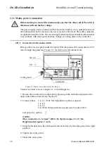
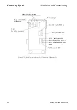
Figure 21 Mains connection inside the cabinet.
Connect as below (also see chapter 11, Circuit Diagram.):
1. Release the connector from the knob by pressing in the red button located on the
upper side of the connector (see Figure 21).
2. Connect phase
1 to L1 (N.B. Not dependent on phase sequence)
2 to L2
3 to L3
0 to XT26.N(line neutral is needed only for option 432)
and protective earth to
NOTE!
Max. cunductor size is 6 mm
2
(AWG 10). Tighten torque 2.3-2.5 Nm.
Retighten after approx. 1 week.
3. Snap the breaker on to the knob again and check that it is fixed properly in the right
position.
4. Tighten the cable gland.
5. Fasten the cover plate.
PE
Cable gland
Connector
XT 26
Summary of Contents for IRB 6400R
Page 4: ...Description 20 Product Specification IRB 1400 M97A BaseWare OS 3 0 ...
Page 6: ...Introduction 2 Product Manual ...
Page 10: ...Introduction 6 Product Manual ...
Page 12: ...Product Specification IRB 6400R 2 Product Specification IRB 6400R M99 BaseWare OS 3 2 ...
Page 78: ...Accessories 68 Product Specification IRB 6400R M99 BaseWare OS 3 2 ...
Page 80: ...Product Specification RobotWare 2 Product Specification RobotWare for BaseWare OS 3 2 ...
Page 82: ...Introduction 4 Product Specification RobotWare for BaseWare OS 3 2 ...
Page 104: ...Interbus S 3 2 26 Product Specification RobotWare for BaseWare OS 3 2 ...
Page 110: ...I O Plus 3 2 32 Product Specification RobotWare for BaseWare OS 3 2 ...
Page 128: ...PalletWare 50 Product Specification RobotWare for BaseWare OS 3 2 ...
Page 132: ...Safety 2 Product Manual ...
Page 148: ...System Description CONTENTS Page 2 Product Manual ...
Page 158: ...Structure System Description 12 Product Manual ...
Page 160: ...Computer System System Description 14 Product Manual ...
Page 164: ...I O System System Description 18 Product Manual ...
Page 168: ...Safety System System Description 22 Product Manual ...
Page 170: ...External Axes System Description 24 Product Manual ...
Page 174: ...Installation and Commissioning CONTENTS Page 4 Product Manual IRB 6400R ...
Page 196: ...On Site Installation Installation and Commissioning 26 Product Manual IRB 6400R ...
Page 270: ...Installing the Control Program Installation and Commissioning 100 Product Manual IRB 6400R ...
Page 292: ...Maintenance CONTENTS Page 2 Product Manual IRB 6400R ...
Page 299: ...Maintenance Product Manual IRB 6400R 9 Figure 4 Lubricating gearbox axis 1 4 3 1 2 ...
Page 312: ...Troubleshooting Tools CONTENTS Page 2 Product Manual ...
Page 350: ...Troubleshooting Tools 40 Product Manual ...
Page 352: ...Fault tracing guide 2 Product Manual ...
Page 362: ...Fault tracing guide 12 Product Manual ...
Page 375: ...Motor units Repairs 12 Product Manual IRB 6400R ...
Page 401: ...Arm System Repairs 38 Product Manual IRB 6400R ...
Page 409: ...Cabling Repairs 46 Product Manual IRB 6400R ...
Page 441: ...Special Tools List Repairs 80 Product Manual IRB 6400R ...
Page 479: ...Part List and Spare Parts Product Manual IRB 6400R 38 ...
Page 480: ...Part List and Spare Parts Product Manual IRB 6400R 39 ...
Page 481: ...Part List and Spare Parts Product Manual IRB 6400R 40 ...