


Arm System
Repairs
30
Product Manual IRB 6400R
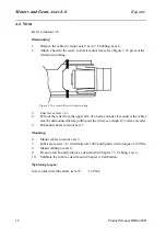
Mounting:
9.
Place the upper arm in position.
NOTE! Mount the left side first, complete, robot seen from behind! See Figure 11.
10.
Mount V-ring (5) and distance ring (6) on shaft (3).
11.
Lubricate the M80 thread and the cone with Molycote 1000.
12.
Mount the shaft (3) in the lower arm. Tighten with a torque of 300 Nm.
13.
Apply Loctite 243 on stop screw (2) and tighten with 34 Nm.
14.
Mount sealing ring (4), turn the largest diameter inwards.
15.
Mount and grease the bearing (7).
16.
Insert the NILOS ring (8).
17.
Insert the distance ring (9).
18.
Mount the KM nut (1). Apply Loctite 243 and tighten the nut to 180 Nm, then
loosen the nut again and tighten with a torque of 90 Nm.
19.
Then mount the right side, paragraphs 12-18 (similar to the left side, except for
the distance ring (6).
20.
Mount the parallel bar.
21.
Mount the cabling as described Chapter 7.2 Robot Harness / Customer Harness.
22.
Mount the balancing units as described in 5.1, Dismounting balancing unit.
NOTE! Remove the 2 extra mechanical stops!
Tightening torques:
Shafts, item (3):
300 Nm
KM nut, item (1):
90 Nm
Screws, clamps, item 8/31.3.3:
300 Nm
Summary of Contents for IRB 6400R
Page 4: ...Description 20 Product Specification IRB 1400 M97A BaseWare OS 3 0 ...
Page 6: ...Introduction 2 Product Manual ...
Page 10: ...Introduction 6 Product Manual ...
Page 12: ...Product Specification IRB 6400R 2 Product Specification IRB 6400R M99 BaseWare OS 3 2 ...
Page 78: ...Accessories 68 Product Specification IRB 6400R M99 BaseWare OS 3 2 ...
Page 80: ...Product Specification RobotWare 2 Product Specification RobotWare for BaseWare OS 3 2 ...
Page 82: ...Introduction 4 Product Specification RobotWare for BaseWare OS 3 2 ...
Page 104: ...Interbus S 3 2 26 Product Specification RobotWare for BaseWare OS 3 2 ...
Page 110: ...I O Plus 3 2 32 Product Specification RobotWare for BaseWare OS 3 2 ...
Page 128: ...PalletWare 50 Product Specification RobotWare for BaseWare OS 3 2 ...
Page 132: ...Safety 2 Product Manual ...
Page 148: ...System Description CONTENTS Page 2 Product Manual ...
Page 158: ...Structure System Description 12 Product Manual ...
Page 160: ...Computer System System Description 14 Product Manual ...
Page 164: ...I O System System Description 18 Product Manual ...
Page 168: ...Safety System System Description 22 Product Manual ...
Page 170: ...External Axes System Description 24 Product Manual ...
Page 174: ...Installation and Commissioning CONTENTS Page 4 Product Manual IRB 6400R ...
Page 196: ...On Site Installation Installation and Commissioning 26 Product Manual IRB 6400R ...
Page 270: ...Installing the Control Program Installation and Commissioning 100 Product Manual IRB 6400R ...
Page 292: ...Maintenance CONTENTS Page 2 Product Manual IRB 6400R ...
Page 299: ...Maintenance Product Manual IRB 6400R 9 Figure 4 Lubricating gearbox axis 1 4 3 1 2 ...
Page 312: ...Troubleshooting Tools CONTENTS Page 2 Product Manual ...
Page 350: ...Troubleshooting Tools 40 Product Manual ...
Page 352: ...Fault tracing guide 2 Product Manual ...
Page 362: ...Fault tracing guide 12 Product Manual ...
Page 375: ...Motor units Repairs 12 Product Manual IRB 6400R ...
Page 401: ...Arm System Repairs 38 Product Manual IRB 6400R ...
Page 409: ...Cabling Repairs 46 Product Manual IRB 6400R ...
Page 441: ...Special Tools List Repairs 80 Product Manual IRB 6400R ...
Page 479: ...Part List and Spare Parts Product Manual IRB 6400R 38 ...
Page 480: ...Part List and Spare Parts Product Manual IRB 6400R 39 ...
Page 481: ...Part List and Spare Parts Product Manual IRB 6400R 40 ...


