background image

Note

Action

xx2200000347

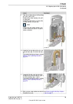
Reassemble the Robifix connector. Start
by connecting the male and female con-
nectors.

28

Mount the Robifix connectors (pos. 1) to
the welding gun by tightening the screws
(pos. 2) with a tightening torque of 3 Nm.

29

Mount new cable ties (pos. 3) to secure
the cables.

30

See

Remove/reassemble the protective

cover on page 79

.

xx2200000359

When parts are reassembled, reassemble
the protective cover.

Tip

If the protective cover does not fit, adjust
the two screws (pos. 1) holding the sec-
ondary leader.
Keep in mind the alignment of the mov-
able leaf shunt.

31

Product manual - GWT C9

101

3HAA010198-001 Revision: A

© Copyright 2022 ABB. All rights reserved.

5 Repair

5.7 Replacement of the transformer

Continued

Summary of Contents for GWT C9

Page 1: ...ROBOTICS Product manual GWT C9 ...

Page 2: ...Trace back information Workspace Robots and Applications version a79 not checked in Published 2022 03 16 at 16 53 39 Skribenta version 5 5 019 ...

Page 3: ...Product manual GWT C9 Document ID 3HAA010198 001 Revision A Copyright 2022 ABB All rights reserved Specifications subject to change without notice ...

Page 4: ...ranty by ABB for losses damage to persons or property fitness for a specific purpose or the like In no event shall ABB be liable for incidental or consequential damages arising from use of this manual and products described herein This manual and parts thereof must not be reproduced or copied without ABB s written permission Keep for future reference Additional copies of this manual may be obtaine...

Page 5: ...nnectors 28 2 3 2 2 Water cooling 33 2 4 Variants and offers 33 2 4 1 Complete offer 34 2 4 2 Standard offer 34 2 4 2 1 Gun arms 35 2 4 2 2 Interface brackets 37 2 4 3 Customized offer 39 2 4 4 Accessories 40 2 5 Technical details and requirements 40 2 5 1 Actuator 41 2 5 2 Transformer MFDC 42 2 5 3 Water cooling system 43 2 5 4 Temperature and hygrometry 44 2 5 5 Robot and controller requirements...

Page 6: ...orage and decommissioning 111 6 1 Introduction 112 6 2 Storage 113 6 3 Decommissioning 114 6 4 Environmental information 115 7 Reference information 115 7 1 Introduction 116 7 2 Applicable safety standards 117 7 3 Unit conversion 118 7 4 Bolt screws tightening torques 118 7 4 1 Bolt and screws 119 7 4 2 Standard tightening torques 120 7 5 Standard toolkit 122 7 6 Special tools 123 7 7 Lifting acce...

Page 7: ...requisites A maintenance repair installation personnel working with an ABB robot must be trained by ABB and have the required knowledge of mechanical and electrical installation repair maintenance work References Document name Document description 3HAC050979 001 Application manual Spot options Customer documentation GWT C9 mechanical drawing Customer documentation GWT C9 electrical drawing RobiFix...

Page 8: ...also include specific safety information when dangerous steps are to be performed Read more in the chapter Safety on page 9 Illustrations The product is illustrated with general figures that does not take painting or protection type in consideration Likewise certain work methods or general information that is valid for several product models can be illustrated with illustrations that show a differ...

Page 9: ...rs carried out by in experienced or non qualified personnel Foreign objects Force majeure Nation region specific regulations To protect personnel the complete system must be designed and installed in accordance with the safety requirements set forth in the standards and regulations of the country where the robot is installed To be observed by the supplier of the complete system The integrator is r...

Page 10: ...ing slipping tripping and falling hazards Safe design Emergency stop buttons must be positioned in easily accessible places so that the robot can be stopped quickly If any of the buttons do not stop all the robot work cell motion each emergency stop button must be marked and placed so there is no risk for using the wrong button stop If more than one emergency stop is provided each should indicate ...

Page 11: ...verview The protective stops and emergency stops are described in the product manual for the controller Product manual GWT C9 11 3HAA010198 001 Revision A Copyright 2022 ABB All rights reserved 1 Safety 1 1 2 Protective stop and emergency stop ...

Page 12: ... 1 Fire extinguishing Note Use a CARBON DIOXIDE CO2 extinguisher in the event of a fire in the robot 12 Product manual GWT C9 3HAA010198 001 Revision A Copyright 2022 ABB All rights reserved 1 Safety 1 2 1 Fire extinguishing ...

Page 13: ...controller before proceeding work Note Switch off all main power switches in a MultiMove system Spot welding cabinet Wait for 5 minutes to let the capacitors discharge after the power has been switched off DANGER Even if the main switch is switched off the capacitors can cause electric shock if not given the time to discharge Product manual GWT C9 13 3HAA010198 001 Revision A Copyright 2022 ABB Al...

Page 14: ...nings or other parts inside the product after work has been performed If any part of the safety system is not working as intended commissioning or test run shall not be performed until the issues are resolved by authorized personnel Safety risks during operational disturbances Corrective maintenance must only be carried out by qualified personnel who are familiar with the entire installation as we...

Page 15: ... cause eye injuries There might also be a risk of processing chips dust being spread due to the cleaning functionality of the cutter Use goggles within the production cell Protective shoes At a workplace where lifting and handling of parts occur protective shoes shall always be used Padlock When intervention is needed the power supply must be turned off to the machines within the danger area and t...

Page 16: ...pot welding cabinet A danger of high voltage is associated with for example the following parts Be aware of stored electrical energy weld timer in the spot welding cabinet DC link and Ultracapacitor bank unit in the controller Units such as I O modules can be supplied with power from an external source The main supply main switch The transformers The power unit The control power supply 230 VAC The...

Page 17: ...use your hand at some distance to feel if heat is radiating from the potentially hot component before actually touching it Wait until the potentially hot component has cooled if it is to be removed or handled in any other way Do not put anything on hot metal surfaces e g paper or plastic Product manual GWT C9 17 3HAA010198 001 Revision A Copyright 2022 ABB All rights reserved 1 Safety 1 3 3 Hot pa...

Page 18: ...s situation which if not avoided will result in ser ious injury DANGER Signal word used to indicate a potentially hazardous situation which if not avoided could result in serious injury WARNING Signal word used to indicate a potentially hazardous situation related to electrical hazards which if not avoided could result in serious injury ELECTRICAL SHOCK Signal word used to indicate a potentially h...

Page 19: ...T C9 comes with the actuator tuned and the Equalization parameters already prepared Concept For the GWT C9 the gun body mainly consists of the gun arm Its fundamental elements can be categorized as below Gun interface to robot Arms of various standard or custom made shapes Electrodes of various standard or custom made shapes Fluid and electrical connections Protection cover for environmental expos...

Page 20: ...ions used in this manual Explanation Term abbreviation Gun Weld Technique Generation 9 GWT C9 Medium Frequency Direct Current MFDC Mean Time Between Failures MTBF Mean Time To Repair MTTR 20 Product manual GWT C9 3HAA010198 001 Revision A Copyright 2022 ABB All rights reserved 2 Product description 2 2 Terminology ...

Page 21: ...obot Arms of various standard or custom made shapes Electrodes of various standard or custom made shapes Fluid and electrical connections Available as mirrored configuration Protection cover for environmental exposure Continues on next page Product manual GWT C9 21 3HAA010198 001 Revision A Copyright 2022 ABB All rights reserved 2 Product description 2 3 1 Principle ...

Page 22: ...talled on a robot or attached to a pedestal as shown in the images below xx1900001709 xx2200000307 22 Product manual GWT C9 3HAA010198 001 Revision A Copyright 2022 ABB All rights reserved 2 Product description 2 3 1 Principle Continued ...

Page 23: ...n body 2 Arm unit 3 Centering ring 4 Protective cover 5 Electrode bushing 6 Electrode shaft 7 Electrode cap 8 Continues on next page Product manual GWT C9 23 3HAA010198 001 Revision A Copyright 2022 ABB All rights reserved 2 Product description 2 3 2 Detailed views ...

Page 24: ...tributor 3 Cooling pad 4 Actuator 5 Power transformer 6 Transformer 7 Rail 8 Ball carriage 9 Power and signal LeanID 10 Continues on next page 24 Product manual GWT C9 3HAA010198 001 Revision A Copyright 2022 ABB All rights reserved 2 Product description 2 3 2 Detailed views Continued ...

Page 25: ... Electrode cap Tip 2 pcs one on each electrode holder 3 Insert coupling 4 Water hoses 5 Continues on next page Product manual GWT C9 25 3HAA010198 001 Revision A Copyright 2022 ABB All rights reserved 2 Product description 2 3 2 Detailed views Continued ...

Page 26: ... seen in the image below For more detail assembly information see separate Product manual for Robifix References on page 7 xx1900001656 Connectors for DressPack LeanID The 3 circular sockets are prepared for direct connection to the LeanID DressPack xx1600000791 R3 CPS Transformer current sensor and temperature sensor A Continues on next page 26 Product manual GWT C9 3HAA010198 001 Revision A Copy...

Page 27: ...Sin Cos Ref Temperature sensor B R3 SP Motor U V W phases Brake C Product manual GWT C9 27 3HAA010198 001 Revision A Copyright 2022 ABB All rights reserved 2 Product description 2 3 2 1 Electrical connectors Continued ...

Page 28: ...n cause failure to welding equipment reduce the durability of components and produce poor welds Therefore the water flow should be monitored regularly The illustration below shows the water circuits in a welding gun in general Green hose is water inlet Red and black are water outlets xx1900001657 Continues on next page 28 Product manual GWT C9 3HAA010198 001 Revision A Copyright 2022 ABB All right...

Page 29: ...sible configurations for the fixed electrode are shown Water into the electrode runs through the green hose Water out from the electrode runs through the red hose xx1900001693 xx1900001692 xx1900001694 Continues on next page Product manual GWT C9 29 3HAA010198 001 Revision A Copyright 2022 ABB All rights reserved 2 Product description 2 3 2 2 Water cooling Continued ...

Page 30: ...w as a green dashed line From the electrode the water then returns along the path visualized below as a black dashed line xx1900001695 Figure 2 1 Water in Continues on next page 30 Product manual GWT C9 3HAA010198 001 Revision A Copyright 2022 ABB All rights reserved 2 Product description 2 3 2 2 Water cooling Continued ...

Page 31: ...e 2 2 Water out xx1900001658 Figure 2 3 Cooling pipes Continues on next page Product manual GWT C9 31 3HAA010198 001 Revision A Copyright 2022 ABB All rights reserved 2 Product description 2 3 2 2 Water cooling Continued ...

Page 32: ... Water outlet from mobile arm DN10 Connect PROC4 black to LeanID DressPack B Water outlet from fixed arm DN10 Connect PROC3 red to LeanID DressPack C 32 Product manual GWT C9 3HAA010198 001 Revision A Copyright 2022 ABB All rights reserved 2 Product description 2 3 2 2 Water cooling Continued ...

Page 33: ...ndard or mirrored gun body Gun body with standard or customized arm beam and electrodes An interface bracket Optional Accessories for example a deposit bracket Product manual GWT C9 33 3HAA010198 001 Revision A Copyright 2022 ABB All rights reserved 2 Product description 2 4 1 Complete offer ...

Page 34: ... for arm beam See some examples below xx2200000312 Figure 2 5 GWT C9 375x400 D 16 xx2200000311 Figure 2 4 GWT C9 173x300 D 16 xx2200000313 Figure 2 6 GWT C9 260x600 D 16 34 Product manual GWT C9 3HAA010198 001 Revision A Copyright 2022 ABB All rights reserved 2 Product description 2 4 2 1 Gun arms ...

Page 35: ...e bracket Possible positions Rear C in illustration 45 clockwise from rear position AC in illustration Top A in illustration 45 clockwise from top position AB in illustration Front B in illustration xx1900001680 xx1700001409 Continues on next page Product manual GWT C9 35 3HAA010198 001 Revision A Copyright 2022 ABB All rights reserved 2 Product description 2 4 2 2 Interface brackets ...

Page 36: ... Possible position Side E in illustration xx1700001410 xx1900000034 36 Product manual GWT C9 3HAA010198 001 Revision A Copyright 2022 ABB All rights reserved 2 Product description 2 4 2 2 Interface brackets Continued ...

Page 37: ...with customized gun arms The illustration below shows some examples of different customized gun arms xx2200000314 Continues on next page Product manual GWT C9 37 3HAA010198 001 Revision A Copyright 2022 ABB All rights reserved 2 Product description 2 4 3 Customized offer ...

Page 38: ...o be attached at the right side of the gun body The illustration below shows a standard gun body to the left and a mirrored gun body to the right xx2200000315 38 Product manual GWT C9 3HAA010198 001 Revision A Copyright 2022 ABB All rights reserved 2 Product description 2 4 3 Customized offer Continued ...

Page 39: ...ween the GWT C9 and the robot The automatic tool changer allows for an easy and fast change of tools which is useful if the same robot is used with several different tools There is no need to install a tool changer if the robot only handle the GWT C9 since all maintenance and all common repair work on the welding gun can be performed when the welding gun is still attached on the robot Product manu...

Page 40: ...irements Value Parameter 400 VAC Required voltage 12 kg Weight 250 mm Stroke length Max 300 mm s Actuator speed 10x106 cycles MTBF Mean Time Between Failures 40 Product manual GWT C9 3HAA010198 001 Revision A Copyright 2022 ABB All rights reserved 2 Product description 2 5 1 Actuator ...

Page 41: ...meter 600 V Primary voltage 11 1 V Secondary voltage For further information about the transformer see drawing provided with the delivery Product manual GWT C9 41 3HAA010198 001 Revision A Copyright 2022 ABB All rights reserved 2 Product description 2 5 2 Transformer MFDC ...

Page 42: ...water flow through each arm 0 2 mm Minimal filtrationi i Cooling water must be free of contaminants The flow passages in the welding gun can become blocked by contaminants causing restricted water flow and overheating Use only neutral water without chlorides sulfates etc WARNING To ensure the lifetime of diodes in the transformer the transformer must be cooled in the correct way by water flow Weld...

Page 43: ...rature operating 5 C to 30 C Ambient temperature storage 80 Maximal ambient humidity at constant temperature for operating and storage condition Product manual GWT C9 43 3HAA010198 001 Revision A Copyright 2022 ABB All rights reserved 2 Product description 2 5 4 Temperature and hygrometry ...

Page 44: ...eld cabinet through the manipulator to the welding gun Spot welding power cables 2 phases and ground each 25 mm2 Actuator power cable and resolver cable CP CS CBUS Signals from the welding gun temperature etc Stationary GWT C9 The GWT C9 can be installed on a stationary frame pedestal Contact ABB to define the controller configuration 44 Product manual GWT C9 3HAA010198 001 Revision A Copyright 20...

Page 45: ...s and welding spatter outside the cell CAUTION The GWT C9 is intended to be used in normal indoor industrial environments it is not intended for use in extremely dusty humid or explosive environments Work piece WARNING The work piece for welding should be free of oils and other residues that may cause fire poisonous fumes or other inconveniences Electricity WARNING Electrical appliances can be ene...

Page 46: ...fore working with or close to welding with high currents if you are using a pacemaker Movements and lifting of welding gun CAUTION When lifting and moving machinery and equipment the moving parts must be secured from sudden movements and only approved lifting equipment may be used 46 Product manual GWT C9 3HAA010198 001 Revision A Copyright 2022 ABB All rights reserved 2 Product description 2 5 6 ...

Page 47: ...ecautions below should be observed before proceeding with unpacking and installation of the GWT C9 CAUTION Make sure that only qualified installation personnel conforming to all national and local codes are allowed to perform the installation Make sure that the GWT C9 has not been damaged by visual inspection Make sure that the lifting device to be used is dimensioned to handle the weight of the G...

Page 48: ...y cycle does not exceed 40 for the primary side by calculating Duty Cycle Rectifier See how to calculate in the below example Duty Cycle Transformer weld time x welds min x 100 60 s min x frequency 22 cy x 10 welds min x 100 60 s min x 50 hz 6 1 Duty Cycle Rectifier diodes 22cy 22cy on 150 cy off x 100 12 8 Required equipment Product example Equipment Qty See Standard toolkit on page 120 Standard ...

Page 49: ...to the GWT C9 Identification plate To identify the delivery read the identification plate and compare it to the delivery note The identification plate is located on the side of the GWT C9 body and indicates in particular the welding gun type and serial number xx1700002176 Continues on next page Product manual GWT C9 49 3HAA010198 001 Revision A Copyright 2022 ABB All rights reserved 3 Installation...

Page 50: ... contact ABB for complaints before returning the welding gun This is to ensure goods labeling and traceability of the welding gun Carefully repack the welding gun to prevent further damages Make sure that all parts of the packing list have been delivered Tip It is recommended to photograph the unit immediately after unpacking to document the conditions of the delivery Continues on next page 50 Pro...

Page 51: ...aminated by impurities during the transport clean it with a clean lint free cloth Product manual GWT C9 51 3HAA010198 001 Revision A Copyright 2022 ABB All rights reserved 3 Installation and commissioning 3 2 1 Unpacking and acceptance Continued ...

Page 52: ... way CAUTION Always use lifting equipment that are dimensioned for the weight of the GWT C9 indicated in the test protocol Always follow local safety standards and rules regarding the lifting equipment Product example Equipment Qty See Standard toolkit on page 120 Standard toolkit 1 Lifting slings 1 Lifting the GWT C9 CAUTION Always follow local safety standards and rules regarding the lifting pro...

Page 53: ...w the knurled screw pos 1 and remove the pressure washer pos 2 keeping the protect ing cover in place 1 Remove the protecting cover pos 3 2 xx1900001702 Attach lifting slings around the arm and angle bracket and lift the welding gun carefully 3 Product manual GWT C9 53 3HAA010198 001 Revision A Copyright 2022 ABB All rights reserved 3 Installation and commissioning 3 2 2 Handling lifting Continued...

Page 54: ...ery For information about connecting the two halves of the tool changer see the product manual of the tool changer provided with the delivery Required equipment Product example Equipment Qty See Standard toolkit on page 120 Standard toolkit 1 M12 screws class 8 8 10 Installing the GWT C9 using a lift table Note This procedure could be performed if the GWT C9 is attached to a angled interface brack...

Page 55: ...ached to the manipulators 6th axis flange Move the robot to a position where this Lean ID bracket is in a good working high 4 Rotate the 6th axis to create an in line positioning with the welding gun interface bracket 5 Adjust the high of the lift table to ensure that the GWT C9 interface bracket and the Lean ID bracket is in level 6 xx1900001703 Rotate the 6th axis 90 to the left If this is done ...

Page 56: ... Remove the lift table 11 Remove the cover and connect all media like Robifix Electrical cabling and water supply Replace the cover on the gun 12 See Lifting the GWT C9 on page 52 xx1900001709 Rotate the robots 6th axis back to an upright positioning 13 Continues on next page 56 Product manual GWT C9 3HAA010198 001 Revision A Copyright 2022 ABB All rights reserved 3 Installation and commissioning ...

Page 57: ...an long short interface bracket or an interface plate is used 5 Long short interface bracket One person grab the GWT C9 in the welding gun arms and move it to wards the robot The other person adjust the move ment to fit the GWT C9 interface bracket with the dowel pin attached to the Lean ID bracket a Interface plate One person grab the GWT C9 in the welding gun arms and rotate the welding gun 90 u...

Page 58: ...rom the welding gun 7 Remove the cover and connect all media like Robifix Electrical cabling and water supply Replace the cover on the gun 8 See Lifting the GWT C9 on page 52 xx1900001709 Rotate the robots 6th axis back to an upright positioning 9 58 Product manual GWT C9 3HAA010198 001 Revision A Copyright 2022 ABB All rights reserved 3 Installation and commissioning 3 3 Mechanical installation C...

Page 59: ...ired equipment Product example Equipment Qty See Standard toolkit on page 120 Standard toolkit 1 Procedure Note Actions DANGER Turn off all electric power supply water pressure supply air pressure supply to the robot before entering the ro bot working area 1 Make sure that the DressPack is in stalled correct to the robot before connecting the GWT C9 If not in stall the DressPack according to the P...

Page 60: ...rs on page 26 xx1900001683 Connect the three water connections to the corresponding water hoses 6 See Water cooling on page 28 60 Product manual GWT C9 3HAA010198 001 Revision A Copyright 2022 ABB All rights reserved 3 Installation and commissioning 3 4 Connecting electricity and media Continued ...

Page 61: ...ile MOC cfg for the GWT C9 The robot controller has an existing MOC cfg file with specific settings related to the robot and robot system The GWT C9 settings simply needs to be added to this file The motion control file for the welding gun is provided with the GWT C9 Description without ABB controller If the robot controller is not provided by ABB but from another company contact ABB for guidance ...

Page 62: ...This page is intentionally left blank ...

Page 63: ...pedestal before performing any maintenance Precautions The precautions below should be observed before proceeding with the maintenance of the GWT C9 CAUTION Make sure that only qualified installation personnel conforming to all national and local codes are allowed to perform maintenance Welding arms and cooling systems are hot after welding Let them cool down before any intervention All power supp...

Page 64: ...screws and tightening torques See Bolt screws tightening torques on page 118 64 Product manual GWT C9 3HAA010198 001 Revision A Copyright 2022 ABB All rights reserved 4 Maintenance 4 1 Introduction Continued ...

Page 65: ...g gun is posi tioned in a good working position 1 Make sure that all safety aspects are considered before performing any maintenance 2 Most maintenance operations requires that the protective cover is removed This is done by unscrewing the knurled screw pos 1 and remove the pressure washer pos 2 keeping the protecting cover pos 3 in place 3 Perform the required maintenance operations 4 Make sure t...

Page 66: ...at the cables are correctly positioned within the harness Cables harness and connections Verify that all the communication signals function properly See below drawing position 41 and 45 Inspect the condition of the hoses and connectors fit tings and make sure that there is no premature wearing or coolant leaking Make sure that they are correctly positioned within the harness and that they can not ...

Page 67: ...ause severe over heating This will ultimately cause destruction of the C9 welding gun Laminated leaf shunts Every 1 000 000 weld strokes If necessary Retighten the bolted joints See Bolt screws tightening torques on page 118 Replace damage leaf shunts by following proced ure Replacement of the leaf shunts on page 87 xx2200000327 Continues on next page Product manual GWT C9 67 3HAA010198 001 Revisi...

Page 68: ...rease xx2200000324 Inspect the condition of the arms Arm Retighten the bolted joints See Bolt screws tightening torques on page 118 xx2200000321 Inspect the condition of the arms and electrode holders and check tightening torques of the screws Electrode hold ers See Bolt screws tightening torques on page 118 xx2200000326 Continues on next page 68 Product manual GWT C9 3HAA010198 001 Revision A Cop...

Page 69: ...k tightening torques of the screws Robot attach ment See Bolt screws tightening torques on page 118 xx2200000329 xx2200000330 Continues on next page Product manual GWT C9 69 3HAA010198 001 Revision A Copyright 2022 ABB All rights reserved 4 Maintenance 4 2 Maintenance planning Continued ...

Page 70: ...00000320 Inspect the condition of the arm base and check tight ening torques of the screws Arm base See Bolt screws tightening torques on page 118 Tip In order to get access to all 8 screws the movable electrode can be operated xx2200000322 Continues on next page 70 Product manual GWT C9 3HAA010198 001 Revision A Copyright 2022 ABB All rights reserved 4 Maintenance 4 2 Maintenance planning Continu...

Page 71: ...ning torques on page 118 xx2200000331 Inspect the condition of the ball carriage bracket and tightening torques of the screws Ball carriage bracket Tightening torque 7 Nm xx2200000323 Inspection and testing of the GWT C9 by an ABB expert Major overhaul Every 10 000 000 weld strokes Contact ABB service for scheduled maintenance of the actuator Actuator Continues on next page Product manual GWT C9 7...

Page 72: ...xx2200000325 72 Product manual GWT C9 3HAA010198 001 Revision A Copyright 2022 ABB All rights reserved 4 Maintenance 4 2 Maintenance planning Continued ...

Page 73: ...m the current sensor Inspect the wiring See Bolt screws tightening torques on page 118 Tighten the screws with a torque wrench Some screws are loose Verify that its resist ance is about 30 Ohm No or bad feedback from the current sensor Welding current is too high Inspect the wiring Verify modify the ro bot target Electrode cap are not perpendicular to the workpiece Electrode caps has abnormal wear...

Page 74: ... of the tips Stuck electrode tips Dress change the tips Verify that the actual permanent current is lower than the expec ted rated current Secondary current overload See Application manual Spot options 3HAC050979 001 Check the pro grammed force Perform a force calib ration Welding force too low Check change the programmed thick ness Wrong value of the programmed sheet thickness Shock noise when cl...

Page 75: ... the Safety risks related to spot welding on page 45 section before performing any service work DANGER Turn off all electric power hydraulic and pneumatic pressure supplies to the robot pedestal before performing any repair work Precautions The precautions below should be observed before proceeding with the repair of the GWT C9 CAUTION Make sure that only qualified installation personnel conformin...

Page 76: ...s on page 122 Other equipment may be required See references to these in the step by step in structions below Bolts screws and tightening torques See Bolt screws tightening torques on page 118 76 Product manual GWT C9 3HAA010198 001 Revision A Copyright 2022 ABB All rights reserved 5 Repair 5 1 Introduction Continued ...

Page 77: ...stomer doc drawing provided with the delivery Parts should always be replaced by approved parts delivered by ABB Use of unauthorized parts will void the warranty Product manual GWT C9 77 3HAA010198 001 Revision A Copyright 2022 ABB All rights reserved 5 Repair 5 2 Spare parts ...

Page 78: ... section describes the general procedures necessary for all repair work described in this chapter Continues on next page 78 Product manual GWT C9 3HAA010198 001 Revision A Copyright 2022 ABB All rights reserved 5 Repair 5 3 General procedures ...

Page 79: ...00000328 Action Read the introduction section before performing any service work see Introduction on page 75 1 Make sure that all safety aspects are considered before performing any repair work 2 If the welding gun is attached to a robot move the robot so the welding gun is posi tioned in a good working high 3 Continues on next page Product manual GWT C9 79 3HAA010198 001 Revision A Copyright 2022...

Page 80: ...pment is removed before restarting the welding 8 Reassembling the protective cover Action Reassemble the protecting cover pos 3 1 Reassemble the pressure washer pos 2 2 Tighten the knurled screw by hand pos 1 3 Make sure that the working space is cleaned and that all equipment is removed before restarting the welding 4 80 Product manual GWT C9 3HAA010198 001 Revision A Copyright 2022 ABB All right...

Page 81: ... not removed Scotch brite hand pad fine grit 1 See Special tools on page 122 Only if the water hose is removed Scotch brite wheel 1 See Special tools on page 122 Only if the water hose is removed Hand drill machine 1 See Special tools on page 122 See Special tools on page 122 Spot welding gun tip removal tool 1 Procedure Tip If there is a need to replace both electrode holders change one at a time...

Page 82: ...ng for each hose This is done by pushing back the push lock for each hose and gently pull apart the hose from the insert coupling The insert couplings are reached through the holes in the arms 2 Continues on next page 82 Product manual GWT C9 3HAA010198 001 Revision A Copyright 2022 ABB All rights reserved 5 Repair 5 4 Replacement of the electrode holders and water hoses Continued ...

Page 83: ...ite wheel otherwise use a hand pad 6 Lubricate the contact surface with new contact paste Spread the paste evenly over the entire contact surface using a brush 7 xx1900000005 Remove the complete electrode position 1 and copper gasket position 2 from the electrode holder position 3 8 Remove the cooling pipe from the elec trode holder position 4 9 Before replacing the electrode holder remove the ins...

Page 84: ... Assemble the cooling pipe pos 3 to the electrode holder pos 2 with a tightening torque of 7 Nm 13 xx2000002659 Replace the copper gasket pos 2 with a new one Note Lubricate the thread of the bushing pos 1 with contact paste 14 Assemble the electrode bushing pos 1 to the electrode holder pos 3 Use a tightening torque of 60 Nm 15 Continues on next page 84 Product manual GWT C9 3HAA010198 001 Revisi...

Page 85: ...be deformed in any way 16 Replace with the electrode cap pos 1 with a new one Assemble it by gently taping it in place with a hammer with plastic head 17 xx2000002663 xx2000002665 Gently push the electrode holder back into the arm Reconnect the water hoses pos 1 This is done by pushing the hoses into the couplings 18 Continues on next page Product manual GWT C9 85 3HAA010198 001 Revision A Copyrig...

Page 86: ...r in the wrong position a repositioning must be done according to the main assembly drawing Measure the position of the electrode holders and make sure that it matches the values in the main assembly drawing TCP check is required 21 xx1900000019 Tighten the screws and nuts alternately to evenly distribute the force over the clamping connection 22 86 Product manual GWT C9 3HAA010198 001 Revision A ...

Page 87: ... 122 Scotch brite wheel 1 See Special tools on page 122 Hand drill machine 1 Procedure Illustration Action See Remove reassemble the protective cover on page 79 Remove the protective cover 1 xx2200000334 Open movable gun arm to large opening position with the actuator rod fully retrac ted inside the actuator 2 Continues on next page Product manual GWT C9 87 3HAA010198 001 Revision A Copyright 2022...

Page 88: ...her pos 4 5 The leaf shunts and cooling block can now be removed 6 Replace the leaf shunts 7 xx2000002667 xx2000002668 Clean the contact surfaces of the leaf shunts and cooling block with a clean cloth Lubricate the contact surfaces with con tact paste Spread the paste evenly over the entire contact surfaces using a brush 8 Continues on next page 88 Product manual GWT C9 3HAA010198 001 Revision A ...

Page 89: ...shers pos 2 and screws pos 1 Use standard tightening torque according toBolt screws tightening torques on page 118 10 xx2200000336 Assemble the other leaf shunt and the cooling block pressure washers pos 2 and 4 and screws pos 1 and 3 Use standard tightening torque according toBolt screws tightening torques on page 118 11 See Remove reassemble the protective cover on page 79 When parts are reassem...

Page 90: ...Illustration Action See Remove reassemble the protective cover on page 79 Remove the protective cover 1 xx2200000334 Open movable gun arm to large opening position with the actuator rod fully retrac ted inside the actuator 2 See Connecting electricity and media on page 59 Loosen all the connecting media power cable and temperature sensor 3 Continues on next page 90 Product manual GWT C9 3HAA010198...

Page 91: ...rt posi tion before disassembly 4 xx2200000338 Disconnect the LeanID connectors and remove from actuator 5 Continues on next page Product manual GWT C9 91 3HAA010198 001 Revision A Copyright 2022 ABB All rights reserved 5 Repair 5 6 Replacement of the actuator Continued ...

Page 92: ...M16 screw is secured with Loctite 243 so if needed heat the screw pos 7 with a hot air gun or equal to loosen it Use a wrench to hold piston rod coupling in place while loosening the M16 screw 8 xx2200000340 Remove the four nuts holding the actuat or 9 xx2200000341 Position the new actuator and slide it into place pos 2 10 Apply thread locking fluid Loctite 243 to the nuts before reassembling the ...

Page 93: ...3 Place the insulation plate pos 6 and the electrode adapter pos 5 in alignment to the piston rod coupling pos 8 14 Reassemble the screws pos 1 incl washers and sleeves Tighten the screws with a maximum torque of 9 8 Nm 15 xx2200000338 Reconnect the LeanID connectors 16 See Remove reassemble the protective cover on page 79 When parts are reassembled reassemble the protective cover 17 Product manua...

Page 94: ...Action See Remove reassemble the protective cover on page 79 Remove the protective cover 1 xx2200000342 Position the welding gun as shown in il lustration The movable gun arm in opened position 2 Ideally place a lifting table under or just beside the welding gun to use as a ser vice table 3 xx2200000343 Disconnect the three water hoses at the water distributor 4 Continues on next page 94 Product m...

Page 95: ...the two water hoses distribut ing water to the arm 6 xx2200000346 Disconnect the two water hoses connect ing to the secondary leader and the X coupling 7 Continues on next page Product manual GWT C9 95 3HAA010198 001 Revision A Copyright 2022 ABB All rights reserved 5 Repair 5 7 Replacement of the transformer Continued ...

Page 96: ... and tem perature connector from the transformer 9 xx2200000349 Remove the screws pos 1 and pressure plates pos 2 connecting to the fixed and movable leaf shunts 10 xx2100000253 Remove the two screws pos 2 holding the transformer pos 1 11 Continues on next page 96 Product manual GWT C9 3HAA010198 001 Revision A Copyright 2022 ABB All rights reserved 5 Repair 5 7 Replacement of the transformer Cont...

Page 97: ...rest on a lifting table placed under the welding gun 12 xx2200000351 Remove the transformer gently together with the connected parts 13 xx2100000256 Remove the screws pos 1 holding the secondary leaders pos 2 Remove the water couplings pos 3 14 Replace the transformer 15 Continues on next page Product manual GWT C9 97 3HAA010198 001 Revision A Copyright 2022 ABB All rights reserved 5 Repair 5 7 Re...

Page 98: ...nd 18 Reuse the water couplings from the old transformer by reassembling the coup lings on the new transformer Apply thread sealant before assemble Note If the water couplings are damaged re place with new ones 19 xx2200000352 Reassemble the transformer pos 1 with the mounting screws pos 2 two on each side Use standard tightening torque according to Bolt screws tightening torques on page 118 20 Co...

Page 99: ...ader as shown in illusta tion This to ensure that no strain is put on the leaves sideways 22 Now tighten the screws pos 1 with standard tightening torque according toBolt screws tightening torques on page 118 Note Tighten the screws pos 3 with reduced torque of 30 Nm 23 xx2200000354 xx2200000355 Reconnect the three water hoses at the water distributor 24 Continues on next page Product manual GWT C...

Page 100: ... hoses connect ing to the secondary leaders and X coupling 26 xx2200000358 Reconnect the current sensor and temper ature connector pos 1 to the trans former pos 2 27 Continues on next page 100 Product manual GWT C9 3HAA010198 001 Revision A Copyright 2022 ABB All rights reserved 5 Repair 5 7 Replacement of the transformer Continued ...

Page 101: ...pos 3 to secure the cables 30 See Remove reassemble the protective cover on page 79 xx2200000359 When parts are reassembled reassemble the protective cover Tip If the protective cover does not fit adjust the two screws pos 1 holding the sec ondary leader Keep in mind the alignment of the mov able leaf shunt 31 Product manual GWT C9 101 3HAA010198 001 Revision A Copyright 2022 ABB All rights reserv...

Page 102: ...age 75 Required equipment Product example Equipment Qty See Standard toolkit on page 120 Standard toolkit 1 See Special tools on page 122 Scotch brite wheel or hand pad 1 Procedure Note Action See Remove reassemble the protective cover on page 79 Remove the protective cover 1 xx2200000297 Position the welding gun as illustration shows 2 Ideally place a lifting table under or just beside the weldin...

Page 103: ... out the gray signal cable through the arm 7 xx2200000284 Remove the screws pos 1 and pressure plate pos 2 connecting to the fixed leaf shunt Let the cooling pad pos 3 stay connec ted to the cooling hoses 8 Continues on next page Product manual GWT C9 103 3HAA010198 001 Revision A Copyright 2022 ABB All rights reserved 5 Repair 5 8 Replacement of the welding gun arm Continued ...

Page 104: ...arm using a hammer with plastic head 9 xx2200000286 The dowel pin pos 1 will most likely stick to the arm Remove it by pulling it out using a puller tool 10 Continues on next page 104 Product manual GWT C9 3HAA010198 001 Revision A Copyright 2022 ABB All rights reserved 5 Repair 5 8 Replacement of the welding gun arm Continued ...

Page 105: ... in place 11 Gently pull out the electrode holder pos 2 together with the water hoses pos 3 Protect the hose ends so no contamin ants enter 12 xx2200000287 Inspect the new arm for defects Make sure all contact surfaces are clean 13 Continues on next page Product manual GWT C9 105 3HAA010198 001 Revision A Copyright 2022 ABB All rights reserved 5 Repair 5 8 Replacement of the welding gun arm Contin...

Page 106: ...ly over the entire contact surface using a brush 16 xx2200000290 Reassemble the electrode holder and hoses Start by routing the water hoses pos 2 through the arm pos 3 and push the electrode holder pos 1 back into place tighten the screws and nuts loosely pos 4 If the dowel pin pos 5 is stuck to the arm reassemble it to the new arm 17 xx2200000289 Lubricate the contact surface on the leaf shunt an...

Page 107: ...pos 2 This is done by using a steel scale pos 3 20 xx2200000293 Reassemble the two remaining screws pos 1 and tighten all four screws Use standard tightening torque according to Bolt screws tightening torques on page 118 21 xx2200000294 Reroute the signal cable through the arm marked with red in illustration 22 Continues on next page Product manual GWT C9 107 3HAA010198 001 Revision A Copyright 20...

Page 108: ...unt pos 2 using the pressure washer pos 3 and screws pos 4 Use standard tightening torque according to Bolt screws tightening torques on page 118 24 xx2200000296 Reconnect the two water hoses distribut ing water to the arm 25 Continues on next page 108 Product manual GWT C9 3HAA010198 001 Revision A Copyright 2022 ABB All rights reserved 5 Repair 5 8 Replacement of the welding gun arm Continued ...

Page 109: ... touch each other 27 Align the electrode holder with the oppos ite electrode holder Tip Use a set square right angled and hold it to the fixed arm and align the loose electrode holder with the scale 28 Continues on next page Product manual GWT C9 109 3HAA010198 001 Revision A Copyright 2022 ABB All rights reserved 5 Repair 5 8 Replacement of the welding gun arm Continued ...

Page 110: ... done according to the main assembly drawing Measure the position of the electrode holders and make sure that it matches the values in the main assembly drawing TCP check is required 29 See Remove reassemble the protective cover on page 79 Reassemble the protective cover 30 110 Product manual GWT C9 3HAA010198 001 Revision A Copyright 2022 ABB All rights reserved 5 Repair 5 8 Replacement of the we...

Page 111: ...decommissioning the GWT C9 CAUTION Welding arms and cooling systems are hot after welding Let them cool down before any intervention All power supplies to the GWT C9 as well as to other machines within the danger zone must be turned off If required the main switch should be locked Make sure that the cooling system is not pressurized Required equipment Product example Equipment Qty See Standard too...

Page 112: ...e remaining cooling water from the water circuit with compressed air and plug the connec tion ports 1 Protect the nipples and connections from mech anical impact 2 Cover the the welding gun to protect if from dust and other unwanted particles 3 See Temperature and hygrometry on page 43 Store the welding gun were it is protected from direct sunlight and in an place that meets the re quirements rega...

Page 113: ...ese in the step by step in structions in the Repair chapter Procedure Note Action Purge the remaining cooling water from the water circuit with compressed air 1 See Environmental information on page 114 Follow environmental legislation regarding recyc ling 2 See Repair on page 75 If needed disassembly the welding gun by follow ing the steps described in the Repair chapter 3 Product manual GWT C9 1...

Page 114: ... synchronization brackets arms and interface bracket Aluminium Oil and grease Where possible arrange for oil and grease to be recycled Dispose of via an authorized person contractor in accordance with local regulations Do not dispose of oil and grease near lakes ponds ditches down drains or onto soil Incineration must be carried out under controlled conditions in accordance with local regulations ...

Page 115: ... chapter includes general information complementing the more specific information in the different procedures in the manual Product manual GWT C9 115 3HAA010198 001 Revision A Copyright 2022 ABB All rights reserved 7 Reference information 7 1 Introduction ...

Page 116: ... instructions for partially completed machines Safety of machinery Electrical equipment of machines General requirements EN 60204 1 2006 The Low Voltage Directive LVD 2014 35 EU Electromagnetic Compatibility EMC Directive 2014 30 EU Electromagnetic compatibility EMC Part 6 4 Generic stand ards Emission standard for industrial environments EN 61000 6 4 2007 A1 2011 Electromagnetic compatibility EMC...

Page 117: ...ty 39 37 in 3 28 ft 1 m Length 2 21 lb 1 kg Weight 0 035 ounces 1 g Weight 14 5 psi 100 kPa 1 bar Pressure 0 225 lbf 1 N Force 0 738 lbf ft 1 Nm Moment 0 264 US gal 1 L Volume Product manual GWT C9 117 3HAA010198 001 Revision A Copyright 2022 ABB All rights reserved 7 Reference information 7 3 Unit conversion ...

Page 118: ...ue Use the correct tightening torque for each type of screw joint Only use correctly calibrated torque keys Always tighten the joint by hand and never use pneumatic tools Use the correct tightening technique tighten the screw in a slow flowing motion Maximum allowed total deviation from the specified value is 10 Note The bolts used on or provided with the GWT C9 are of 3 different classes 8 8 10 9...

Page 119: ... Nominal G thread dimension 7 Nm G1 8 9 Nm G1 4 15 5 Nm G3 8 26 Nm G1 2 R thread All R threads are coated with a sealing material This coating replaces the conventional sealing ring Simply screw in the R thread by hand and tighten it with 1 or 2 turns with a spanner NPQH fittings Tightening torque Nm Nominal G thread dimension 6 Nm G1 8 7 5 Nm G1 4 9 Nm G3 8 9 Nm G1 2 Product manual GWT C9 119 3HA...

Page 120: ...ed in the table below This way the tools required are the sum of the standard toolkit and any tools listed in the instruction Contents standard toolkit xx1700002219 Tool Qty Bent snipe nose pliers 1 Set of mandrels Ø3 mm Ø10 mm 1 Set square right angled 1 Set of spanners 12 mm 13 mm 14 mm 15 mm 16 mm 19 mm 24 mm 27 mm and 32 mm 1 Torque wrench 10 100 Nm 1 Continues on next page 120 Product manual ...

Page 121: ...times referred to as CHC screws Hammer 1 Ratchet wrench 1 T handle Hex keys 6 mm 1 Hex keys Allen key 1 5 10 mm 9 Hammer with plastic head 1 A clean cloth 1 Brush 1 Thread locking fluid Loctite 243 1 Contact paste Lubripaste DS ES 1 Product manual GWT C9 121 3HAA010198 001 Revision A Copyright 2022 ABB All rights reserved 7 Reference information 7 5 Standard toolkit Continued ...

Page 122: ...ions and also gathered in this section Summary special equipment Product Equipment Qty xx2000002637 Puller tool 1 xx2000002656 Scotch brite hand pad very fine grade 1 xx2000002657 Scotch brite wheel very fine grade 1 xx2000002673 Spot welding gun tip removal tool 1 Hand drill machine 1 Hot air gun 1 Thread sealant Scantech 4000T 1 122 Product manual GWT C9 3HAA010198 001 Revision A Copyright 2022 ...

Page 123: ...lifting accessories is not detailed in the activity procedure but in the instruction delivered with each piece of lifting accessories This implies that the instructions delivered with the lifting accessories should be stored for later reference Product manual GWT C9 123 3HAA010198 001 Revision A Copyright 2022 ABB All rights reserved 7 Reference information 7 7 Lifting accessories and lifting inst...

Page 124: ...This page is intentionally left blank ...

Page 125: ...uipment 15 protective wear 15 R region specific regulations 9 responsibility and validity 9 rubber disposal 114 S safety fire extinguishing 12 signals 18 signals in manual 18 symbols 18 safety risk electric parts 16 hot parts 17 installation 14 operational disturbance 14 service work 14 voltage 16 safety signals in manual 18 safety standards 116 safety zones 10 signals safety 18 stainless steel di...

Page 126: ......

Page 127: ......

Page 128: ...ne 47 22 87 2000 ABB Engineering Shanghai Ltd Robotics Discrete Automation No 4528 Kangxin Highway PuDong District SHANGHAI 201319 China Telephone 86 21 6105 6666 ABB Inc Robotics Discrete Automation 1250 Brown Road Auburn Hills MI 48326 USA Telephone 1 248 391 9000 abb com robotics 3HAA010198 001 Rev A en Copyright 2022 ABB All rights reserved Specifications subject to change without notice ...

Reviews: