


99
1 3 A D D I N G/R EP L AC I N G A U P S M O D U L E
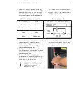
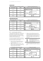
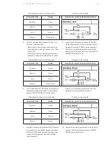
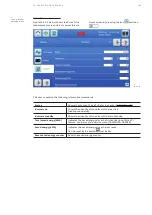
LED indicators status on the module
Display on the module
LED INDICATION
COLOR
SINGLE/DUAL INPUT FEED CONFIGURATION
Rectifier
Green
Bypass
Green
Load
Yellow
Battery
Flashing red
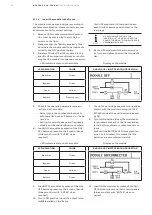
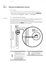
5. Check if the operating parameters are cor-
rectly set in the module.
• Battery type, the number of blocks/cells,
autonomy time, set as “Common” or “Sep-
arate” etc.
• Setting for output voltage and frequency.
• Module and frame identification numbers.
6. Load ON the modules by means of the ON/
OFF button present on its control panels (Al-
ways confirm with “ENTER” when required).
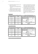
7. Check if the starting sequence is correctly
executed, with the module running in STATIC
BYPASS mode at the end.
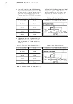
LED indicators status on the module
Display on the module
LED INDICATION
COLOR
SINGLE/DUAL INPUT FEED CONFIGURATION
Rectifier
Green
Bypass
Green
Load
Yellow
Battery
Flashing red
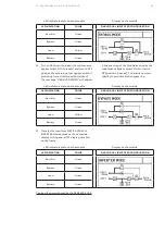
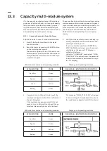
8. Turn to ON position (close) the relative mod-
ule battery breakers present on the frames.
Wait until the BATTERY LED turns green
(approx. 1, 2 minutes), this means that the
batteries are connected and are ok.
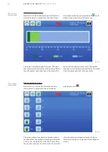
LED indicators status on the module
Display on the module
LED INDICATION
COLOR
SINGLE/DUAL INPUT FEED CONFIGURATION
Rectifier
Green
Bypass
Green
Load
Yellow
Battery
Green
9. Load ON, if previously loaded OFF, all remain-
ing modules in the parallel system by means
of the ON/OFF button present on their con-
trol panels (Always confirm with “ENTER”
when required).
10. Check if the starting sequence is correctly ex-
ecuted, with all modules running in STATIC
BYPASS mode at the end.


