


78
DPA 2 50 S 4 50 - 2 50 K W
O P ER AT I N G M A N UA L
—
10 Commissioning
—
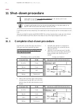
10.1
Start-up procedure
NOTE
PLEASE REFER TO CHAPTER "
5.2.1.4-LED STATUS INDICATORS
"
FOR THE MEANING OF THE LED
INDICATORS, COLOURS AND BEHAVIOUR
HE OPERATIONS DESCRIBED IN THIS CHAPTER MUST BE PERFORMED BY A SERVICE ENGINEER FROM THE
MANUFACTURER OR BY AN AGENT CERTIFIED BY THE MANUFACTURER
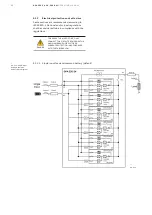
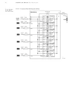
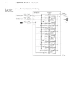
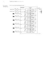
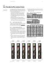
10.1.1 UPS parallel installation situation
before switching it on
1. Make sure the fuses for the supply of
UPS-System in the input distribution board
on site have been removed.
2. Make sure all the input, output and battery
connections have been correctly performed.
3. Make sure all battery breakers in the UPS
frame(s) and in the external battery cabinets
are in the OFF position (Open).
4. Verify that the maintenance bypass
switch(es).
Q1
(Optional) is/are in OFF position (Open).
5. Verify that the output isolator/s
Q2
is/are in
OFF position(Open).
6. The general external output isolator (if any)
must be opened. No load must be connected
to the parallel system output.
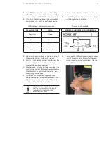
7. Verify that the DIP switch configuration on
each frame in the parallel system is correct.
• Dip switches on Parallel board/s
(see chapter 9.5)
• Dip switches on Customer Interface
board/s (see chapter 9.5).
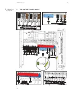
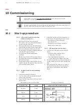
10.1.2 UPS input phase rotation check
1. Insert fuses in the customer distribution
board:
• Single input feed configuration
→
Insert input line fuses.
• Dual input feed configuration
→
Insert Rectifier and Bypass line fuses.
2. Check the input phase rotation and sequence
on each frame for both Rectifier and By-pass
lines.
3. Remove the Rectifier fuses and, in case of
dual input feed configuration, also the By-
pass fuses in the customer distribution
board.
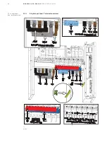
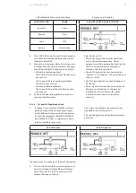
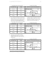
10.1.3 Module installation and parameters
check
1. Insert all modules in the frames.
2. Fix all modules with the supplied screws (2
screws in each module).
3. Insert Rectifier fuses line in customer distri-
bution board.
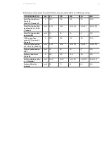
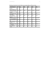
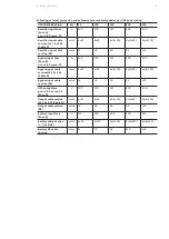
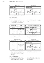
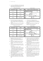
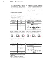
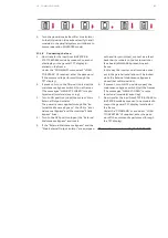
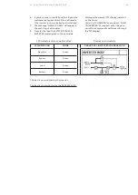
LED indicators status on all modules
Display on all modules
LED INDICATION
COLOR
SINGLE INPUT FEED CONFIGURATION
Rectifier
Green
Bypass
Green
Load
OFF
Battery
Flashing Red


