


81
10 CO M M I SS I O N I N G
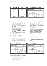
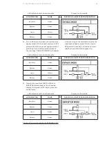
3. Load-ON to INVERTER mode the last module
in the parallel installation (The module in the
uppermost slot of the last frame).
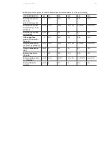
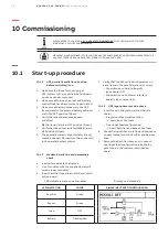
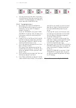
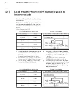
LED indicators status:
Module display:
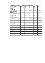
LED INDICATION
COLOR
SINGLE INPUT FEED CONFIGURATION
Rectifier
Green
Bypass
Green
Load
Green
Battery
Flashing Red
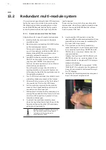
4. As soon as the module is Loaded-ON, the
Green led in the Parallel board inside this
frame will lights up (This is now the “Master”
frame).
5. Verify that the message “UPS now is Master”
is now present in the module event log.
• This is now the “Master” module.
6. Scroll through the module menu “Measure-
ments” and check to make sure that they are
all correct.
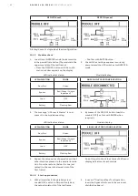
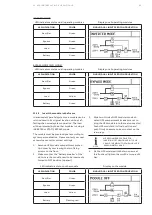
7. Now executed the command “LOAD TO BY-
PASS” from the module display.
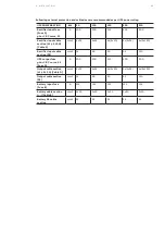
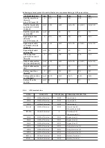
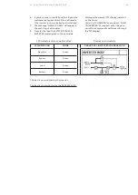
LED indicators status:
Module display:
LED INDICATION
COLOR
SINGLE INPUT FEED CONFIGURATION
Rectifier
Green
Bypass
Green
Load
Yellow
Battery
Flashing Red
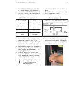
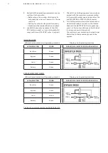
8. Now execute the command “LOAD TO IN-
VERTER” from the module display.
9. Let the module operate in the INVERTER
mode!
10. Load-ON to INVERTER mode the previous
module in the frame (below the one just
tested)
11. As soon as this module is Loaded-ON, the
message “UPS now is Master” is recorded in
its event log.
• This is now the “Master” module.
• The message “UPS now is slave” will be au-
tomatically recorded in the module previ-
ously Loaded-ON (the one above this).
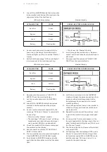
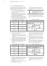
12. Check the module LED indicator status and
the symbols on the display.
13. Execute now the command “LOAD TO BY-
PASS” in this module.
14. The two modules must now switch together
from INVERTER to STATIC BYPASS mode.
15. Switch back to INVERTER mode and verify
again that both modules switch at the same
time.
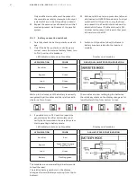
16. Let the two modules run in the INVERTER
mode and repeat the same sequences of op-
erations with all modules present in the
frame (always from uppermost to lowest
module position).
17. Move to the previous frame in the parallel in-
stallation (if any) and close the relative out-
put isolator Q2.
18. Repeat the same series of operations start-
ing with the module in the uppermost posi-
tion.
19. As soon as the first module present in the
frame is Loaded-ON, the Green led of the rel-
ative Parallel board will lights up (This is now
the “Master” frame).
20. The Green led in the last frame will automati-
cally switch OFF.
21. Verify always that the message “UPS now is
Master” is recorded in the event log of the
last module Loaded ON to INVERTER mode
and the message “UPS now is slave” is re-
corded in the previous ones.


