


83
10 CO M M I SS I O N I N G
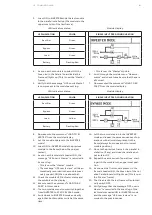
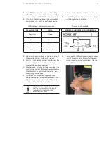
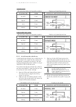
5. Turn the general mains Rectifier Line isolator
to the ON position (closed) and verify that all
modules in the parallel system switch back to
normal operation (INVERTER mode)
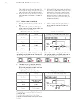
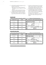
10.1.8 Connecting the load
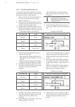
1. Now transfer the load from INVERTER to
STATIC BYPASS mode by means of one mod-
ule display or the general TFT display in-
stalled on the frame.
Under the “COMMAND” menu select “LOAD
TO BYPASS” (If required, enter the password
if the command is performed through the
TFT display).
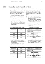
2. If present, turn to the ON position (close) the
maintenance bypass switch Q1 on all frames.
(The messages “MAN BYP CLOSED” is regis-
tered on all module(s) event log).
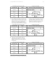
3. Turn to ON position (close) the system “Main
External Output Isolator”.
The power is now supplied through the “Ex-
ternal Maintenance Bypass”, the UPS/s “Inter-
nal manual Bypass” and the modules “Static
Bypass” lines!
4. Turn to the OFF position (open) the “External
Maintenance Bypass” and lock it.
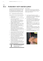
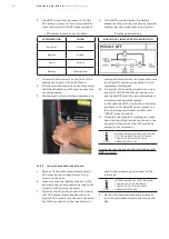
5. If the “External Maintenance Bypass” and the
“Main External Output Isolator” are equipped
with auxiliary switch(es), connect as a feed-
back their terminals to the Customer Inter
face board/s NW40085 present in each
frame.
In this way the Inverter on all modules pres-
ent in the parallel installation will be locked
while the External Maintenance Bypass is
closed (Set to ON position).
6. If present, turn to OFF position (open) the
maintenance bypass switch Q1 all the frames.
(The messages “MAN BYP OPEN” is regis-
tered on all module(s) event log).
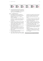
7. Now transfer the load from STATIC BYPASS to
INVERTER mode by means of one module dis-
play or the general TFT display installed on
the frame.
Under the “COMMAND” menu select “LOAD
TO INVERTER” (If required, enter the pass-
word if the command is performed through
the TFT display).
The load is now protected by the 250 S4 UPS


