


43
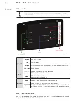
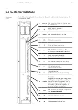
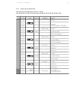
• Each UPS unit is supplied with the customer interface ports which provide information about the
UPS system as follow:
—
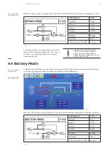
5.3-1
1
Slot 1/2
Slot for optional Modem / Ethernet card
and SNMP Card
2
JD1
RS232 Sub D9 / female PC /
laptop connection
3
SD card
Slot for Secure Digital (SD) cards
4
USB
PC / laptop connection
5
J3
Graphical display connection
6
S1
DIP-SWITCH for customer interface
configuration (see chapters 3.3 and 9.5)
7
J2
(RJ 45) Multi-drop connection
(multi-cabinet configuration)
8
X3
UPS inputs and 12VDC source (X3 5/6)
9
X2
UPS outputs dry ports
(potential free contacts)
10
X1
Interlock Function
(External maintenance bypass switch)
11
X1 sync
Sync input:
Allows for synchronization of the output of
a UPS system (single UPS or parallel sys-
tem) with another UPS system, another
electrical equipment (AC) or an external
grid. See Service Manual. Optional Syn-
chronization Feature is required
12
SW1
DIP-SWITCH for parallel UPS configuration
(see chapters 3.3 and 9.5)
13
JD1
Input parallel BUS connector
14
JD2
Output parallel BUS connector
—
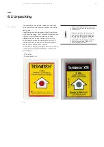
5.3 Customer interface
—
5.3-1: Customer
interface
5 CO N T R O L & M O N I TO R I N G


