


92
DPA 2 50 S 4 50 - 2 50 K W
O P ER AT I N G M A N UA L
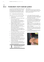
13.1.2 Insert the module in the frame
The module must be previously set according to
system personalization. Please contact your near-
est service center for correct settings.
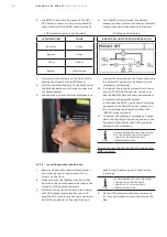
1. Remove UPS module compartment protec-
tion cover by unscrewing the two fixing
screws on the front.
2. Make sure that the “Battery breaker” of the
slot where the module need to be inserted is
turned to the OFF position (open).
3. Slide two thirds of the UPS module into the
specific UPS compartment (make sure not to
plug the UPS module into the rear connector).
Push UPS module to its final position and
push firmly to assure good contact on the
rear plugs.
NOTE
WE RECOMMEND 2 PEOPLE FOR
INSERTION OF THE MODULE INTO THE
FRAME. THE WEIGHT OF ONE MODULE IS
APPROXIMATELY 66 KG
4. Fix the UPS module with the two screws on
its front and tighten them with a torque of 6
Nm.
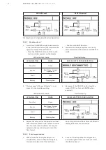
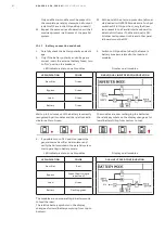
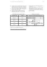
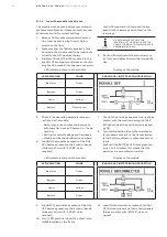
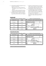
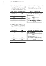
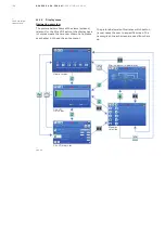
LED indicators status on the module
Display on the module
LED INDICATION
COLOR
SINGLE/DUAL INPUT FEED CONFIGURATION
Rectifier
Green
Bypass
Green
Load
Yellow
Battery
Flashing red
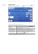
5. Check if the operating parameters are cor-
rectly set in the module.
• Battery type, the number of blocks/cells,
autonomy time, set as “Common” or “Sepa-
rate” etc.
• Setting for output voltage and frequency.
• Module and frame identification numbers.
6. Load ON the modules by means of the ON/
OFF buttons present on their control panels
(Always confirm with “ENTER” when
required).
7. Check if the starting sequence is correctly ex-
ecuted, with the module running in STATIC
BYPASS mode at the end (Inverter is locked
by Q1).
8. Turn to ON position (close) the module bat-
tery breakers present on the frames and ex-
ternal battery cabinets or racks breakers or
fuses.
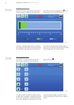
Wait until the BATTERY LED turns green (ap-
prox. 1 to 2 minutes), this means that the
batteries are connected and are OK.
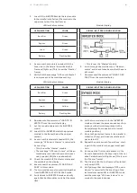
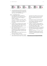
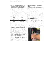
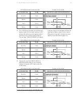
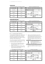
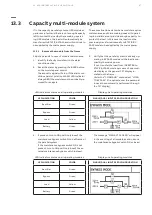
LED indicators status on the module
Display on the module
LED INDICATION
COLOR
SINGLE/DUAL INPUT FEED CONFIGURATION
Rectifier
Green
Bypass
Green
Load
Yellow
Battery
Green
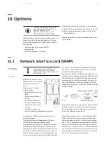
9. Load OFF the modules by means of the ON/
OFF buttons present on their control panels
(Always confirm with “ENTER” when
required).
10. Turn to ON position (close) the output isola-
tor
Q2
installed on the frame.
11. Load ON the modules by means of the ON/
OFF buttons present on their control panels
(Always confirm with “ENTER” when re-
quired).


