


88
DPA 2 50 S 4 50 - 2 50 K W
O P ER AT I N G M A N UA L
—
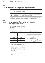
12.2
Load transfer from maintenance bypass to
inverter mode
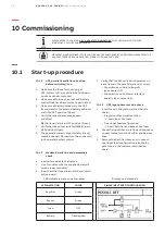
Situation of UPS parallel system before starting
the procedure:
The load is supplied directly by Input Mains power
(Via maintenance bypass switches
Q1
if present
on the frames or external maintenance bypass
switch).
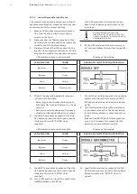
All modules are turned OFF
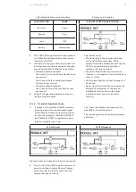
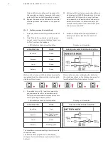
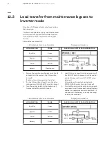
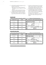
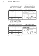
LED indicators status on all modules
Display on all modules
LED INDICATION
COLOR
SINGLE/DUAL INPUT FEED CONFIGURATION
Rectifier
Green
Bypass
Green
Load
Yellow
Battery
Flashing red
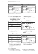
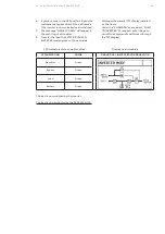
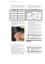
1. Be sure the maintenance bypass switches Q1
installed in all frames is in the ON position
(closed)!
If not, perform this operation first of all.
2. If in the ON position (closed), turn the exter-
nal bypass switch to the OFF position (open).
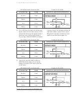
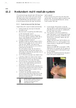
3. Turn the output isolator QS installed on all
frames to the ON position (closed).
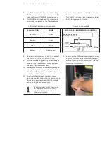
4. Load ON one by one all modules by means of
the ON/OFF buttons present on their control
panels (Always confirm with “ENTER” when
required).
All modules will now start operating in
STATIC BYPASS mode (Inverter is locked).
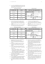
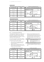
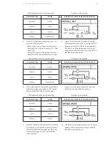
5. Turn to ON position (close) the battery break-
ers present on all frames and external battery
cabinets or racks breakers or fuses (Wait 1, 2
minutes until the battery correctly are recog-
nized by the modules).
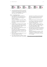
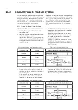
LED indicators status on all modules
Display on all modules
LED INDICATION
COLOR
SINGLE/DUAL INPUT FEED CONFIGURATION
Rectifier
Green
Bypass
Green
Load
Yellow
Battery
Green


