62 Planning the electrical installation
Selecting the control cables
General rules
All control cables must be shielded.
The control cable shield should be earthed directly in the converter. The other end of the
shield should be left unconnected or earthed indirectly via a high frequency, high voltage
capacitor of a few nanofarads (eg, 3.3 nF / 3000 V). The screen can also be earthed
directly at both ends if they are in the same earth line with no significant voltage drop
between the end points.
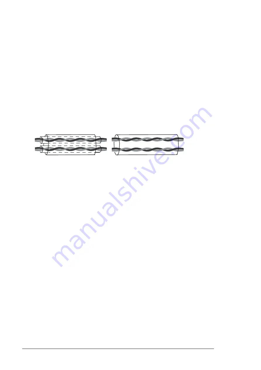
Use a double shielded twisted pair cable (see figure a) for analog signals. This type of
cable is recommended for the pulse encoder signals also. Employ one individually
shielded pair for each signal. Do not use common return for different analog signals.
A double shielded cable is the best alternative for low voltage digital signals but single
shielded twisted multipair cable (figure b) is also usable.
Run analog and digital signals in separate, shielded cables.
Relay controlled signals, providing their voltage does not exceed 48 V, can be run in the
same cables as digital input signals. It is recommended that the relay controlled signals be
run as twisted pairs.
Relay cable
The cable type with braided metallic screen (eg, ÖLFLEX LAPPKABEL, Germany) has
been tested and approved by ABB.
Control panel cable
In remote use, the cable connecting the control panel (if any) to the converter must not
exceed 3 metres (10 ft). The cable type tested and approved by ABB is used in control
panel option kits. Control panel or cable is not included in the converter delivery. For
control panel, contact local ABB representative.
Routing the cables
Route the rotor cable away from other cable routes. It is recommended that the rotor
cable, grid cable and control cables be installed on separate trays. Avoid long parallel runs
of rotor cables with other cables in order to decrease electromagnetic interference caused
by the rapid changes in the rotor voltage.
Where control cables must cross grid cables and rotor cables, make sure they are
arranged at an angle as near to 90 degrees as possible. Do not run extra cables through
the converter.
The cable trays must have good electrical bonding to each other and to the grounding
electrodes. Aluminium tray systems can be used to improve local equalizing of potential.
a
Double shielded twisted multipair
cable
b
Single shielded twisted multipair
cable
Summary of Contents for ACS800-67LC
Page 1: ... ABB WIND TURBINE CONVERTERS ACS800 67LC wind turbine converters Hardware manual ...
Page 4: ......
Page 16: ...16 Safety instructions ...
Page 22: ...22 Introduction to the manual ...
Page 42: ...42 Operation principle and hardware description ...
Page 52: ...52 Mechanical installation ...
Page 79: ...Electrical installation 79 3 3 Rotor side cable connection terminals U2 V2 W2 ...
Page 92: ...92 Maintenance 4 6 5 5 ...
Page 103: ...Maintenance 103 Bussmann fuses Mersen fuses ...
Page 109: ...Maintenance 109 5 6 7 ...
Page 131: ...Technical data 131 Declaration of incorporation ...
Page 136: ...136 Dimension drawings ACS800 67LC 1075 0575 7 and 1375 0575 7 ...
Page 137: ...Dimension drawings 137 With 400 mm wide incoming cubicle option C111 ...
Page 138: ...138 Dimension drawings ACS800 67LC 1375 1125 7 ...
Page 139: ...Dimension drawings 139 With 400 mm wide incoming cubicle option C111 ...
Page 140: ...140 Dimension drawings ACS800 67LC 1595 0865 7 and 2035 1125 7 ...
Page 141: ...Dimension drawings 141 With 400 mm wide incoming cubicle option C111 ...
Page 143: ...Dimension drawings 143 Options 2H370 and C111 Option 1H371 ...
Page 144: ...144 Dimension drawings Options 1H371 and C111 Options 2H371 and C111 ...
Page 145: ...Dimension drawings 145 Option H378 Options H378 and C111 ...
Page 147: ...Dimension drawings 147 Option 2H372 ...
Page 148: ...148 Dimension drawings Option 3H372 ...
Page 149: ...Dimension drawings 149 Option 1H373 ...
Page 150: ...150 Dimension drawings Option 2H373 ...
Page 151: ...Dimension drawings 151 Option 3H373 ...


