background image

2

1

3

4

5

6

7

8

9

10

11

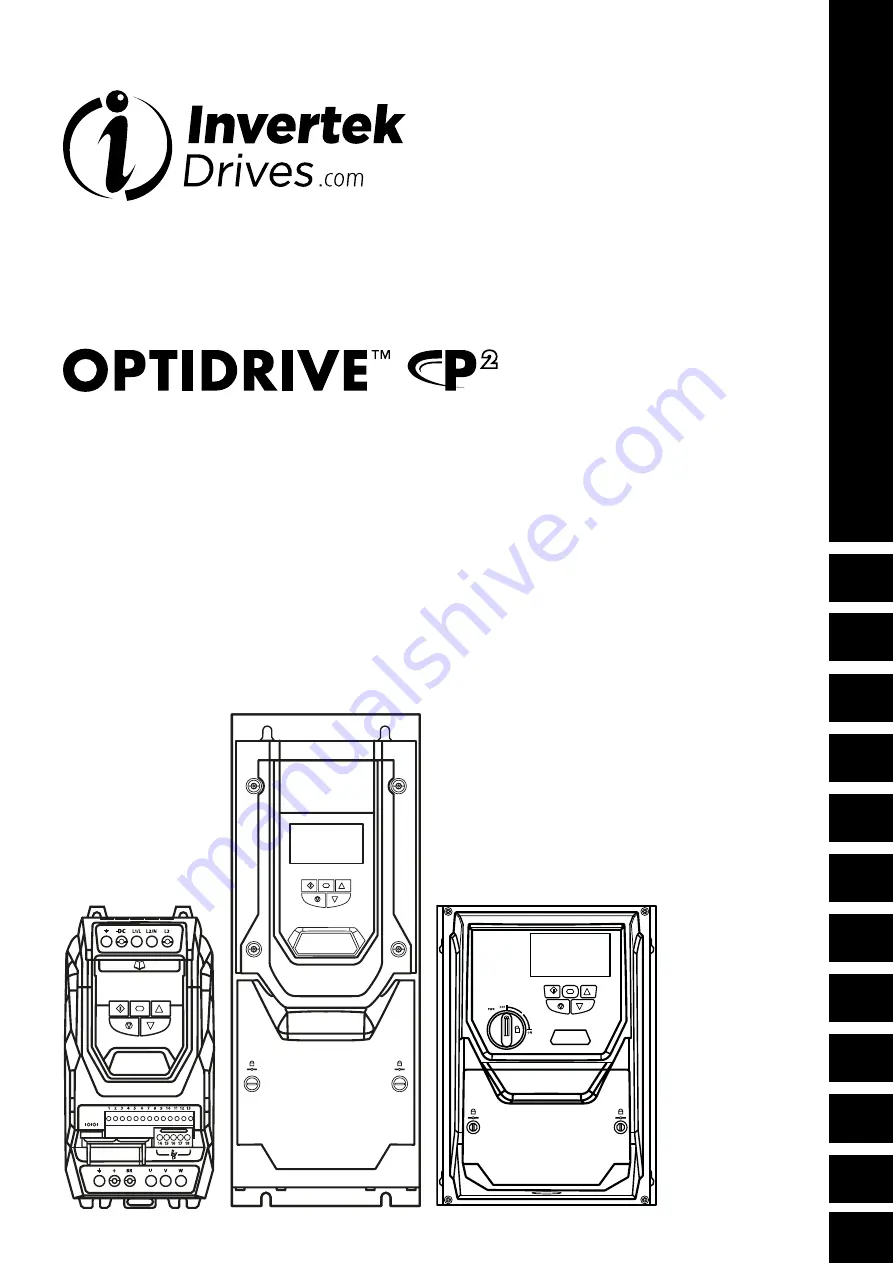
User Guide

AC Variable Speed Drive 

0.75 - 160kW / 1HP - 250HP 
200 - 480V 1 / 3 Phase Input

General Information 

and Ratings

Quick Start Up

Mechanical Installation

Electrical Installation

Keypad and Display Operation

Parameters

Extended  

Parameters

Serial  

Communications

Control Terminal  

Functions

Technical Data

Troubleshooting

Summary of Contents for Optidrive ODP-2

Page 1: ... 1HP 250HP 200 480V 1 3 Phase Input General Information and Ratings Quick Start Up Mechanical Installation Electrical Installation Keypad and Display Operation Parameters Extended Parameters Serial Communications Control Terminal Functions Technical Data Troubleshooting ...

Page 2: ...ctions 24 4 1 1 IP66 Switched Version Integrated Control Switch and Potentiometer Wiring 25 4 12 Motor Thermal Overload Protection 25 4 13 EMC Compliant Installation 26 4 14 Safe Torque Off 27 5 Keypad and Display Operation 31 5 1 OLED Keypad and Display Layout 31 5 2 LED Keypad and Display Layout 31 5 3 Selecting the Language on the OLED Display 31 5 4 Additional Display Messages 32 5 5 Changing ...

Page 3: ...acturing defects from the date of manufacture The manufacturer accepts no liability for any damage caused during or resulting from transport receipt of delivery installation or commissioning The manufacturer also accepts no liability for damage or consequences resulting from inappropriate negligent or incorrect installation incorrect adjustment of the operating parameters of the drive incorrect ma...

Page 4: ... of Machinery In particular the machine manufacturer is responsible for ensuring that the electrical equipment complies with EN60204 1 and providing a disconnecting device which must be one of the following types A switch disconnector utilization category AC 23B EN 60947 3 A circuit breaker suitable for isolation in accordance with EN 60947 2 A disconnector with an integrated auxiliary contact tha...

Page 5: ...ines for Mounting IP66 Units 1 1 1 1 12 15 16 16 17 5 Select the correct power and motor cables according to local wiring regulations or code noting the maximum permissible sizes 10 2 Input Output Power and Current Ratings 68 6 For IT Supply network or any power supply type where the phase earth voltage may exceed the phase phase voltage such as ungrounded supplies disconnect the EMC filter before...
Page 6: ...V HVAC Product Series PCB Coating N Standard Localised Coating C Full Conformal Coating Display S 7 Segment LED Display T OLED Text Display Generation Frame Size Voltage Code 1 1 10 Volt 2 230 Volt 4 400 Volt 5 525 Volt 6 600 Volt Enclosure 2 IP20 4 IP40 D IP66 with Internal Disconnect N IP55 Non Switched S IP55 Switched X IP66 Non Switched Y IP66 Switched Brake Chopper 1 No Brake Chopper 4 Intern...

Page 7: ...P20 Models IP55 Models IP66 Models On right hand side when viewed from the front On right hand side when viewed from the front On the top surface 2 3 Understanding the Rating Label The product rating label provides the following information Key 1 Model Code 2 Enclosure Type and IP Rating 3 Firmware Version 4 Serial Number 5 Technical Data Supply Voltage 6 Technical Data Maximum continuous output c...

Page 8: ...42 SN 2 4 1 2 ODP 2 24220 3KF42 SN 2 2 ODP 2 24030 3HF42 SN 3 5 8 2 ODP 2 24400 3KF42 SN 4 ODP 2 24050 3HF42 SN 5 9 5 2 ODP 2 34055 3KF42 SN 5 5 ODP 2 34075 3HF42 SN 7 5 14 3 ODP 2 34075 3KF42 SN 7 5 ODP 2 34100 3HF42 SN 10 18 3 ODP 2 341 10 3KF42 SN 1 1 ODP 2 34150 3HF42 SN 15 24 3 ODP 2 44150 3KF42 TN 15 ODP 2 44200 3HF42 SN 20 30 4 ODP 2 44185 3KF42 TN 18 5 ODP 2 44250 3HF42 SN 25 39 4 ODP 2 44...

Page 9: ... 24 4 ODP 2 44150 3KF4N SN 15 ODP 2 44200 3HF4N SN 20 30 4 ODP 2 44185 3KF4N SN 18 5 ODP 2 44250 3HF4N SN 25 39 4 ODP 2 44220 3KF4N SN 22 ODP 2 44300 3HF4N SN 30 46 4 ODP 2 54300 3KF4N SN 30 ODP 2 54040 3HF4N SN 40 61 5 ODP 2 54370 3KF4N SN 37 ODP 2 54050 3HF4N SN 50 72 5 ODP 2 64045 3KF N SN 45 ODP 2 64060 3HF N SN 60 90 6 ODP 2 64055 3KF N SN 55 ODP 2 64075 3HF N SN 75 1 10 6 ODP 2 64075 3KF N S...

Page 10: ...urrent A Frame Size Non Switched Switched Non Switched Switched ODP 2 24075 3KF4X TN ODP 2 24075 3KF4Y TN 0 75 ODP 2 24010 3HF4X TN ODP 2 24010 3HF4Y TN 1 2 2 2 ODP 2 24150 3KF4X TN ODP 2 24150 3KF4Y TN 1 5 ODP 2 24020 3HF4X TN ODP 2 24020 3HF4Y TN 2 4 1 2 ODP 2 24220 3KF4X TN ODP 2 24220 3KF4Y TN 2 2 ODP 2 24030 3HF4X TN ODP 2 24030 3HF4Y TN 3 5 8 2 ODP 2 24400 3KF4X TN ODP 2 24400 3KF4Y TN 4 ODP...

Page 11: ...oducts please refer to UL listing NMMS E226333 The drive can be operated within an ambient temperature range as stated in section 10 1 Environmental For IP20 units installation is required in a pollution degree 1 environment For IP55 IP66 units installation in a pollution degree 2 environment is permissible UL Listed ring terminals lugs must be used for all bus bar and grounding connections Refer ...

Page 12: ... 418 16 46 160 6 30 240 9 45 400 15 75 125 4 92 125 4 92 9 2 20 3 5 486 19 13 222 8 74 260 10 24 460 18 1 1 175 6 89 175 6 89 18 1 39 9 Mounting Bolts Tightening Torques Frame Size Metric UNF Frame Size Required Torque 2 M4 8 Control Terminals All 0 5 Nm 4 5 lb in 3 M4 8 Power Terminals 2 3 1 Nm 9 lb in 4 M8 5 16 4 2 Nm 18 lb in 5 M8 5 16 5 4 Nm 35 5 lb in NOTE The IP20 Frame Size 4 Chassis can ob...

Page 13: ...20 28 520 20 47 8 0 31 270 10 63 235 9 25 175 6 89 4 25 0 17 7 5 0 30 23 50 7 6 865 34 06 830 32 68 840 33 07 10 0 39 330 12 99 330 12 99 200 7 87 5 5 0 22 1 1 0 43 55 121 2 7 1280 50 39 1245 49 02 1255 49 41 10 0 39 360 14 17 330 12 99 200 7 87 5 5 0 22 1 1 0 43 89 196 2 Mounting Bolts Tightening Torques Frame Size Metric UNF Frame Size Required Torque 4 M8 8 Control Terminals All 0 5 Nm 4 5 lb i...

Page 14: ... Ib 2 257 10 12 220 8 66 200 7 87 29 1 12 239 9 41 188 7 40 178 7 01 4 2 0 17 8 5 0 33 4 8 10 6 3 310 12 20 277 10 89 252 9 90 33 1 31 266 10 47 21 1 8 29 200 7 87 4 2 0 17 8 5 0 33 7 7 16 8 Mounting Bolts Tightening Torques Frame Size Metric UNF Frame Size Required Torque 2 M4 8 Control Terminals All 0 5 Nm 4 5 lb in 3 M4 8 Power Terminals 2 3 1 Nm 9 lb in 3 Mechanical Installation ...

Page 15: ...s of airborne dust corrosive gases or liquids conductive contaminants such as condensation carbon dust and metallic particles and sprays or splashing water from all directions High moisture salt or chemical content environments should use a suitably sealed non vented enclosure The enclosure design and layout should ensure that the adequate ventilation paths and clearances are left to allow air to ...

Page 16: ...Units Before mounting the drive ensure that the chosen location meets the environmental condition requirements for the drive shown in section 10 1 Environmental on page 68 The drive must be mounted vertically on a suitable flat surface The minimum mounting clearances as shown in the table below must be observed The mounting site and chosen mountings should be sufficient to support the weight of th...

Page 17: ...low mark the locations required for drilling Suitable cable glands to maintain the ingress protection of the drive are required Gland holes for power and motor cables are pre moulded into the drive enclosure recommended gland sizes are shown above Gland holes for control cables may be cut as required ON OFF PWR ON OFF PWR Drive Size X Above Below Y Either Side Cable Gland Sizes mm in mm in Frame P...

Page 18: ...retaining screws indicated until the screw slot is vertical 3 10 2 Frame Size 4 3 10 3 Frame Size 5 Using a suitable flat blade screwdriver rotate the two retaining screws indicated until the screw slot is vertical Using a suitable flat blade screwdriver rotate the four retaining screws indicated until the screw slot is vertical Terminal Cover Release Screws 3 Mechanical Installation ...

Page 19: ...s a suitable operating environment this should include Ambient temperature is at or below that set out in section 10 1 Environmental Heat sink fans freely rotating and dust free The Enclosure in which the drive is installed should be free from dust and condensation furthermore ventilation fans and air filters should be checked for correct air flow Checks should also be made on all electrical conne...

Page 20: ...onnections located at the bottom All other units have power terminals located at the bottom 4 1 1 Electrical Power Connections Key Page A 4 2 Protective Earth PE Connection 21 B 4 3 Incoming Power Connection 22 C 4 3 Incoming Power Connection 22 D External Isolator Disconnect E 4 3 3 Fuse Circuit Breaker Selection 22 F 4 3 4 Optional Input Choke 22 G 4 13 EMC Compliant Installation 26 H 4 6 Motor ...

Page 21: ...l industrial safety regulations and or electrical codes To meet UL regulations UL approved ring crimp terminals should be used for all ground wiring connections The integrity of all ground connections should be checked periodically 4 2 2 Protective Earth Conductor The Cross sectional area of the PE Conductor must be at least equal to that of the incoming supply conductors 4 2 3 Motor Ground The dr...

Page 22: ...ly with any local codes or regulations in place In general type gG IEC 60269 or UL type J fuses are suitable however in some cases type aR fuses may be required The operating time of the fuses must be below 0 5 seconds Where allowed by local regulations suitably dimensioned type B MCB circuit breakers of equivalent rating may be utilised in place of fuses providing that the clearing capacity is su...

Page 23: ...supplies This is indicated on the nameplate of the motor This operational voltage is normally selected when installing the motor by selecting either STAR or DELTA connection STAR always gives the higher of the two voltage ratings Incoming Supply Voltage Motor Nameplate Voltages Connection 230 230 400 Delta 400 400 690 400 230 400 Star 4 8 Connecting a Brake Resistor Optidrive P2 units feature an i...

Page 24: ...lected by parameters as follows Analog Input 1 Format Selection Parameter P2 30 Analog Input 2 Format Selection Parameter P2 33 These parameters are described more fully in section 8 1 Parameter Group 2 Extended Parameters on page 44 The function of the analog input e g for speed reference or PID feedback for example is defined by parameters P1 12 and P1 13 The function of these parameters and ava...

Page 25: ...ntrol switch activates the first two digital inputs as follows Switch Position DI1 ON OFF ON DI2 ON ON OFF 4 12 Motor Thermal Overload Protection 4 12 1 Internal Thermal Overload Protection The drive has an in built motor thermal overload function this is in the form of an I t trP trip after delivering 100 of the value set in P 08 for a sustained period of time e g 150 for 60 seconds 4 12 2 Motor ...

Page 26: ...ion of a standard cable within a suitable steel or copper tube is also acceptable 3 A cable suitable for fixed installation with relevant mains voltage A shielded type cable is not necessary 4 A shielded cable with low impedance shield Twisted pair cable is recommended for analog signals 5 The cable shield should be terminated at the motor end using an EMC type gland allowing connection to the mot...

Page 27: ... by carrying out a thorough risk and hazard analysis the outcome of the analysis should provide an estimate of the possible hazards furthermore determine the risk levels and identify any needs for risk reduction The STO function should be evaluated to ensure it can sufficiently meet the risk level required 4 14 2 What STO Provides The purpose of the STO function is to provide a method of preventin...

Page 28: ...ot be relied upon as a fail safe method When using permanent magnet motors and in the unlikely event of a multiple output power devices failing then the motor could effectively rotate the motor shaft by 180 p degrees Where p denotes number of motor pole pairs 4 14 4 STO Operation When the STO inputs are energised the STO function is in a standby state if the drive is then given a Start signal comm...

Page 29: ...ircuit below section 4 13 1 Recommended Installation for EMC Compliance on page 26 should also be followed The drive should be wired as illustrated below the 24Vdc signal source applied to the STO input can be either from the 24Vdc on the drive or from an External 24Vdc power supply 4 14 8 Recommended STO Wiring Using an External 24Vdc Power Supply Using the Drives On board 24Vdc Supply Twisted Pa...

Page 30: ...top command given to the drive as per the start source method selected in P1 13 o De energise the STO inputs Drive will display InHibit o Give a start command as per the start source method selected in P1 13 and check that the drive still displays Inhibit and that the operation is in line with the section 4 14 4 STO Operation and section 4 14 5 STO Status and Monitoring With the motor running norm...

Page 31: ...eter edit mode and to store parameter changes Up Button Used to increase speed in real time mode or to increase parameter values in parameter edit mode Down Button Used to decrease speed in real time mode or to decrease parameter values in parameter edit mode STOP 37kW 400V 3Ph 5 2 LED Keypad and Display Layout NAVIGATE Used to display real time information to access and exit parameter edit mode a...

Page 32: ...ss the Navigate key for 1 second The display will show the motor power kW If P 10 0 pressing the Navigate key for 1 second will display the motor speed RPM 5 4 Additional Display Messages Auto Tuning in Progress External 24VDC Supply Overload Switching Frequency Reduction Mains Loss Maintenance Time Elapsed LED Display Not Indicated Not Indicated Not Indicated OLED Display P2 01 P2 01 P2 01 P2 01 ...

Page 33: ...om the drive memory the following procedure is used Factory Parameter Reset LED Display User Parameter Reset LED Display Factory Parameter Reset OLED Display User Parameter Reset OLED Display P2 01 P2 01 P2 01 P2 01 P2 01 P2 01 Stop P Def Stop Stop U Def Stop 15kW 400V 3Ph 50 0Hz 15kW 400V 3Ph P1 08 30 0 3 0 30 0A 15kW 400V 3Ph Press and hold the Up Down Start and Stop keys for 2s The display show...

Page 34: ...ble parameter group will be selected 5 8 3 Setting a Parameter to the Minimum Value 0 Whilst editing a parameter value press the Up and Down keys simultaneously The parameter will be set to the lowest possible value 5 8 4 Adjusting Individual Digits When editing parameter values and making large changes e g setting the motor rated speed from 0 to 1500RPM it is possible to directly select the param...

Page 35: ... Rated Frequency o P1 10 Optionally Motor Rated Speed Define the operating speed limits o P1 01 Maximum Frequency or Speed o P1 02 Minimum Frequency or Speed Define the acceleration and deceleration times used when starting and stopping the motor or changing speed o P1 03 Acceleration Time o P1 04 Deceleration Time Select where the drive should receive it s command signals from and determine what ...

Page 36: ...d to increase the available braking torque P1 06 Energy Optimiser 0 1 0 0 Disabled 1 Enabled When enabled the Energy Optimiser attempts to reduce the overall energy consumed by the drive and motor when operating at constant speeds and light loads The output voltage applied to the motor is reduced The Energy Optimiser is intended for applications where the drive may operate for some periods of time...

Page 37: ...ernal PID controller 4 Fieldbus Control Control via Modbus RTU if no fieldbus interface option is present otherwise control is from the fieldbus option module interface 5 Slave Mode The drive acts as a Slave to a connected Optidrive operating in Master Mode 6 CAN bus Control Control via CAN bus connected to the RJ45 serial interface connector P1 13 Digital Input Source Select 0 21 1 Defines the fu...

Page 38: ... If no option module is fitted control is through the Modbus RTU interface Digital Input 1 must be closed to allow operation 5 Slave Mode Master Drive From Master Optidrive P2 provides an inbuilt Master Slave function A single drive acts as the Master and connected Slave drives will mimic the starting and stopping along with the following the output frequency with any scaling applied Digital Input...

Page 39: ...nputs are momentarily active simultaneously the drive stops using Fast Stop Ramp Time P 24 FAST STOP P2 25 Normally Closed Falling Edge Open momentarily to FAST STOP the drive using Fast Stop Ramp Time P 24 E TRIP Normally Closed External Trip input When the input opens momentarily the drive trips showing or depending on P2 33 setting See section 4 12 2 Motor Thermistor Connection on page 25 for f...

Page 40: ...2 03 REF On On P2 04 REF 8 STOP RUN FWD REV DI3 DI4 Preset Speed DECEL P1 04 DECEL P8 1 1 Off Off P2 01 REF On Off P2 02 REF Off On P2 03 REF On On P2 04 REF 8 STOP RUN FWD REV DI3 DI4 Preset Speed P1 12 REF PR REF Off Off P2 01 REF On Off P2 02 REF Off On P2 03 REF On On P2 04 REF 10 STOP RUN FWD REV NO INC SPD NO DEC SPD P1 12 REF1 P2 01 REF 11 STOP RUN FWD STOP RUN REV P1 12 REF PR REF Analog I...

Page 41: ... FWD STOP NC NO START REV Analog Input AI1 P1 12 REF P2 01 REF 1 When P1 12 0 and P 1 13 10 or 20 the Motorised Pot Keypad reference is automatically selected to be the Selected Speed Reference 7 3 Example Connection Schematics P1 13 Setting 1 4 11 14 24V DIN1 DIN2 DIN3 10V AIN1 0V 0V AIN2 STO STO 1 2 3 4 5 6 7 8 9 10 11 12 13 24VDC 24VDC 24VDC 24VDC Enable Disable Enable Disable Run Forward Run F...

Page 42: ... AOUT 2 AOUT 2 STO STO STO STO STO STO STO STO STO STO P1 13 Setting 3 5 13 15 24V DIN1 DIN2 DIN3 10V AIN1 0V 0V AIN2 STO STO 1 2 3 4 5 6 7 8 9 10 11 12 13 24VDC 24VDC 24VDC 24VDC Enable Disable Enable Disable Run Forward Run Forward Reverse Forward Reverse Forward Run Reverse Run Reverse P1 12 REF P2 01 REF P1 12 REF AI2 REF P1 12 REF P2 01 REF P1 12 REF I2 REF 10 VDC 10 VDC 10 VDC 10 VDC AIN 1 A...

Page 43: ...d Run Reverse INC SPEED INC SPEED 10 VDC 10 VDC DEC SPEED DEC SPEED 0 V 0 V AOUT 1 AOUT 1 0 V 0 V P1 12 REF P2 01 REF P1 12 REF P2 01 REF AOUT 2 AOUT 2 STO STO STO STO P1 13 Setting 21 24V DIN1 DIN2 DIN3 10V AIN1 0V 0V AIN2 STO STO 1 2 3 4 5 6 7 8 9 10 11 12 13 24 VDC NO Push Start Forward NC Push Stop NO Push Start Reverse 10VDC AIN 1 0V AOUT 1 0V P1 12 REF P2 01 REF AOUT 2 STO STO 7 Control Term...

Page 44: ...ively and will not hold any output frequency within the defined band If the frequency reference applied to the drive is within the band the Optidrive output frequency will remain at the upper or lower limit of the band P2 11 Analog Output 1 Terminal 8 Function Select 0 11 8 Digital Output Mode Logic 1 24V DC 0 Drive Enabled Running Logic 1 when the Optidrive is enabled Running 1 Drive Healthy Logi...

Page 45: ...ler 0 100 P2 14 Analog Output 2 Terminal 11 Format See Below 0 to10V 0 to 20mA 4 to 20mA 10 to 0V 20 to 0mA 20 to 4mA P2 15 User Relay 1 Output Terminals 14 15 16 Function select 0 14 1 Setting Function Logic 1 when 0 Drive Enabled Running The Optidrive is enabled Running 1 Drive Healthy No fault or trip condition exists on the drive 2 At Target Frequency Speed Output frequency matches the setpoin...

Page 46: ... and 14 parameters P2 16 and P2 17 must be used together to control the behaviour The output will switch to Logic 1 when the selected signal exceeds the value programmed in P2 16 and return to Logic 0 when the signal falls below the value programmed in P2 17 P2 19 Adjustable Threshold 1 Upper Limit Analog Output 2 Relay Output 2 P2 20 200 0 100 0 P2 20 Adjustable Threshold 1 Lower Limit Analog Out...

Page 47: ... Scaling 1 Actual Speed Digital Speed x P2 29 2 Actual Speed Digital Speed x P2 29 Analog Input 1 Reference 3 Actual Speed Digital Speed x P2 29 x Analog Input 1 Reference P2 29 Slave Speed Scaling Factor 500 0 500 0 100 0 Used in conjunction with P2 28 P2 30 Analog Input 1 Terminal 6 Format See Below Setting Signal Format 0 to 10 Volt Signal Uni polar 10 to 0 Volt Signal Uni polar 10 to 10 Volt S...

Page 48: ...ere the Optidrive is configured for multiple speed references typically Hand Auto control or Local Remote control when switched to keypad mode by a digital input the drive will continue to operate at the last operating speed 3 Preset Speed 8 Following a stop and restart the Optidrive will always initially run at Preset Speed 8 P2 08 4 Minimum Speed Terminal Enable Following a stop and restart the ...

Page 49: ...PID Reference Setpoint Source Select 0 2 0 0 PID Reference Setpoint Source Select P3 06 is used 1 Analog Input 1 Setpoint Analog Input 1 as displayed in P0 01 is used 2 Analog Input 2 Setpoint Analog Input 2 as displayed in P0 02 is used P3 06 PID Digital Reference Setpoint 0 0 100 0 0 0 When P3 05 0 this parameter sets the preset digital reference setpoint used for the PID Controller Where the fe...

Page 50: ...4 High Performance Motor Control Overview Parameters relating to the motor control are located together in Group 4 These parameters allow the user to Select the motor type to match the connected motor Carry out an autotune Define the torque limits and setpoint source for control methods that support this vector control methods only Optidrive P2 can operate with both Asynchronous Induction Motors t...

Page 51: ...d Permanent Magnet motors including BLDC produce an output voltage known as the Back EMF when the shaft is rotated The user must ensure that the motor shaft cannot rotate at a speed where this Back EMF exceeds the voltage limit for the drive otherwise damage can occur The following parameter settings are necessary before attempting to operate the motor Ensure advanced parameter access is enabled b...

Page 52: ...eed Vector For speed control of BLDC motors with Trapezoidal back EMF 6 Syn RM Speed Vector For speed control of Synchronous Reluctance motors P4 02 Motor Parameter Auto tune Enable 0 1 0 When set to 1 the drive immediately carries out a non rotating autotune to measure the motor parameters for optimum control and efficiency Following completion of the autotune the parameter automatically returns ...

Page 53: ...to limit the current P4 08 Minimum Motoring Torque Limit P4 08 500 0 150 0 Active only in Vector Speed or Vector Torque motor control modes P4 01 0 or 1 Sets a minimum torque limit whereby the when the Optidrive is enabled it will always attempt to maintain this torque on the motor at all times whilst operating NOTE This parameter should be used with extreme care as the drive output frequency will...

Page 54: ...ither communication method the steps to establish a connection between the PC and drive are as follows Download and install the Optitools Studio PC software to the PC Start the software and select the Parameter Editor function If the drive address has been changed in parameter P5 01 ensure that in the Optitools Studio software the Network Scan Limit setting in the lower left corner of the screen i...

Page 55: ...eatsink Temperature 0 to 100 0 to 100 C 5 User register 1 User Defined Register 1 Value 6 User register 2 User Defined Register 1 Value 7 P0 80 value User Selected data value P5 13 Fieldbus Ramp Control 0 1 0 0 Fieldbus Ramp Control This option must be selected if the drive acceleration and deceleration ramps are to be controlled from the fieldbus P5 07 must also be set to 1 to enable this functio...

Page 56: ... 0 0 P6 10 Function Block Program Enable 0 Disabled 0 1 Enabled P6 11 Speed Hold Time on Enable 0 250s 0s P6 12 Speed Hold DC Injection Time on Disable 0 250s 0s P6 13 Hoist Mode Brake Release Time 0 0 5 0s 0 2s P6 14 Hoist Mode Brake Apply Time 0 0 5 0s 0 3s P6 15 Hoist Mode Pre Torque Level 0 0 200 0 8 0 P6 16 Hoist Mode Pre Torque Timeout 0 0 25 0s 5 0s P6 17 Torque Limit Trip Time 0 0 25 0s 0 ...

Page 57: ...od in V F Mode Sets the motor alignment time in PM modes P7 13 Vector Mode Derivative 0 00 1 00 0 00 Derivative speed loop gain applied in Vector control modes P7 14 Low Frequency Torque Boost Current 0 0 100 0 0 0 For PM Motors applies a torque boost current at low frequency x P1 08 P7 15 Low Frequency Torque Boost Frequency Limit 0 0 50 0 0 0 For PM motors determines the frequency x P1 09 when t...

Page 58: ... P9 19 Reference Select Bit 1 P9 20 Reference Select Bit 2 P9 21 Preset Speed Select Bit 0 P9 22 Preset Speed Select Bit 1 P9 23 Preset Speed Select Bit 2 P9 24 Acceleration Ramp Select Bit 0 P9 25 Acceleration Ramp Select Bit 1 P9 26 Deceleration Ramp Bit 0 P9 27 Deceleration Ramp Bit 1 P9 28 MOP Up Source P9 29 MOP Down Source P9 30 Speed Limit Switch Forward P9 31 Speed Limit Switch Reverse P9 ...

Page 59: ...19 Motor Rotor Resistance Rr Ω P0 20 DC Bus Voltage V P0 21 Drive Temperature C P0 22 Remaining Service Time Hours P0 23 Operating Time Heatsink 85ᵒC HH MM SS P0 24 Operating Time High Ambient Temperature HH MM SS P0 25 Rotor Speed Hz RPM P0 26 Energy consumption kWh kWh P0 27 Energy Consumption MWh MWh P0 28 Drive firmware version N A P0 29 Drive Type N A P0 30 Drive serial number N A P0 31 Drive...

Page 60: ...Frequency input reference Hz RPM P0 60 Calculated slip Hz RPM P0 61 Relay Hysteresis value Hz RPM P0 62 Droop speed Hz RPM P0 63 Post ramp speed reference Hz RPM P0 64 Effective switching frequency kHz P0 65 Drive life time HH MM SS P0 66 Function block program ID N A P0 67 Fieldbus torque reference P0 68 User ramp value S P0 69 I2C error count N A P0 70 Option module type N A P0 71 Fieldbus inter...

Page 61: ... obtain the correct Register address The telegram structure is as follows Command 03 Read Holding Registers Master Telegram Length Slave Response Length Slave Address 1 Byte Slave Address 1 Byte Function Code 03 1 Byte Function Code 03 1 Byte 1st Register Address 2 Bytes Byte Count 1 Byte No Of Registers 2 Bytes 1st Register Value 2 Bytes CRC Checksum 2 Bytes 2nd Register Value 2 Bytes Etc CRC Che...

Page 62: ... Bit 8 No Function The Upper Byte will contain the relevant fault number in the event of a drive trip Refer to section 1 1 1 Fault Messages for a list of fault codes and diagnostic information 7 Output Frequency R Output frequency of the drive to one decimal place e g 123 12 3 Hz 8 Output Current R Output current of the drive to one decimal place e g 105 10 5 Amps 9 Output Torque R Motor output to...

Page 63: ...tion NMT 000h Network management Sync 080h Synchronous message COB ID can be configured to other value Emergency 080h Node address Emergency message COB ID can be configured to other value PDO1 TX 180h Node address Process data object PDO1 is pre mapped and enabled by default PDO2 is pre mapped and disabled by default Transmission mode COB ID and mapping can be configured PDO1 RX 200h Node address...

Page 64: ...12 6 9 3 5 Supported PDO Transmission Types Various transmission modes can be selected for each PDO For RX PDO the following modes are supported Table 3 RX PDO Transmission Mode Transmission Type Mode Description 0 240 Synchronous The received data will be transferred to the drive active control register when the next sync message is received 254 255 Asynchronous The received data will be transfer...

Page 65: ...gned 32 N 00000580h Node ID 1400h 0 RX PDO1 comms param No of entries RO Unsigned 8 N 2 1 RX PDO1 COB ID RW Unsigned 32 N 40000200h Node ID 2 RX PDO1 transmission type RW Unsigned 8 N 254 1401h 0 RX PDO2 comms param No of entries RO Unsigned 8 N 2 1 RX PDO2 COB ID RW Unsigned 32 N C0000300h Node ID 2 RX PDO2 transmission type RW Unsigned 8 N 0 1600h 0 RX PDO1 mapping No of entries RW Unsigned 8 N ...

Page 66: ...00Bh 0 Motor speed Hz RO Unsigned 16 Y 500 50 0Hz 200Dh 0 Motor current RO Unsigned 16 Y 123 12 3A 200Eh 0 Motor torque RO Integer 16 Y 4096 100 0 200Fh 0 Motor power RO Unsigned 16 Y 1234 12 34kW 2010h 0 Drive temperature RO Integer 16 Y 30 30 C 2011h 0 DC bus value RO Unsigned 16 Y 2012h 0 Digital input status RO Unsigned 16 Y 2013h 0 Analog input 1 percentage RO Unsigned 16 Y 2014h 0 Analog inp...

Page 67: ... 9 8 7 6 5 4 3 2 1 0 0 Normal Operation Stop 1 Coast Stop Reset Fast Stop Run Object 200Ah Drive Status Register Status Bit 15 14 13 12 11 10 9 8 7 6 5 4 3 2 1 0 0 Drive Trip Code No Function Drive Healthy Drive Disabled 1 In Standby Maintenance Time reached Inhibit No Function Drive Tripped Drive Enabled 9 Serial Communications ...

Page 68: ...Frame Size Power Rating Input Current Fuse or MCB Type B Maximum Cable Size Rated Output Current Maximum Motor Cable Length Recommended Brake Resistance kW HP A Non UL UL mm AWG kcmil A m ft Ω 2 0 75 1 8 5 10 15 8 8 4 3 100 330 100 2 1 5 1 5 15 2 25 20 8 8 7 100 330 50 2 2 2 1 5 19 5 25 25 8 8 10 5 100 330 35 NOTE Ratings shown above apply to 40 C Ambient temperature For derating information refer...

Page 69: ...205 7 250 300 150 300MCM 202 100 330 6 7 75 50 255 5 315 350 150 300MCM 248 100 330 6 NOTE Ratings shown above apply to 40 C Ambient temperature For derating information refer to section 10 4 1 Operation with single phase supply is possible with 50 derating of the output current capacity The maximum motor cable length stated applies to using a shielded motor cable When using an unshielded cable th...

Page 70: ...240 100 330 6 7 160 250 307 8 400 400 150 300MCM 302 100 330 6 8 200 300 370 500 500 240 450MCM 370 100 330 2 8 250 350 450 500 600 240 450MCM 450 100 330 2 NOTE Ratings shown above apply to 40 C Ambient temperature For derating information refer to section 10 4 1 Derating for Ambient Temperature Operation with single phase supply is possible with 50 derating of the output current capacity The max...

Page 71: ...riation between phase phase voltages allowed All Optidrive P2 units have phase imbalance monitoring A phase imbalance of 3 will result in the drive tripping For input supplies which have supply imbalance greater than 3 typically the Indian sub continent parts of Asia Pacific including China Invertek Drives recommends the installation of input line reactors Alternatively the drives can be operated ...

Page 72: ... A N A 20 30 40 50 IP55 N A 10 10 15 25 N A IP66 N A 10 25 35 50 50 10 4 4 Example of applying Derating Factors A 4kW IP66 drive is to be used at an altitude of 2000 metres above sea level with 12kHz switching frequency and 45 C ambient temperature From the table above we can see that the rated current of the drive is 9 5 Amps at 40 C Firstly apply the switching frequency derating 12kHz 25 deratin...

Page 73: ... Frame Size 4 units have EMC Filter disconnection points only located on the front face of the unit as shown EMC L1 L2 L3 Frame Size 5 Frame Size 5 units have EMC Filter disconnection points only located on the front face of the unit as shown 10 5 2 IP55 IP66 Models These models require disassembly in order to disconnect the EMC filter Disconnection should be carried out only by Invertek Drives Ap...

Page 74: ...e has been successfully completed for the connected motor Check the load mechanically to ensure it is free and that no jams blockages or other mechanical faults exist 05 Hardware Over Current Check the wiring to motor and the motor for phase to phase and phase to earth short circuits Disconnect the motor and motor cable and retest If the drive trips with no motor connected it must be replaced and ...

Page 75: ...g airflow to the drive Reduce the effective switching frequency setting in parameter P2 24 Reduce the load on the motor drive 24 Maximum Torque Limit Exceeded The output torque limit has exceeded the drive capacity or trip threshold Reduce the motor load or increase the acceleration time 25 Output Torque Too Low Active only when hoist brake control is enabled P2 18 8 The torque developed prior to ...

Page 76: ...en received within the watchdog time limit set in P5 06 Check the network master PLC is still operating Check the connection cables Increase the value of P5 06 to a suitable level 52 Communications Option Module Fault Internal communication to the inserted Communication Option Module has been lost Check the module is correctly inserted 53 IO card comms trip Internal communication to the inserted O...

Reviews: