


1.2.1.2.2 Functionality
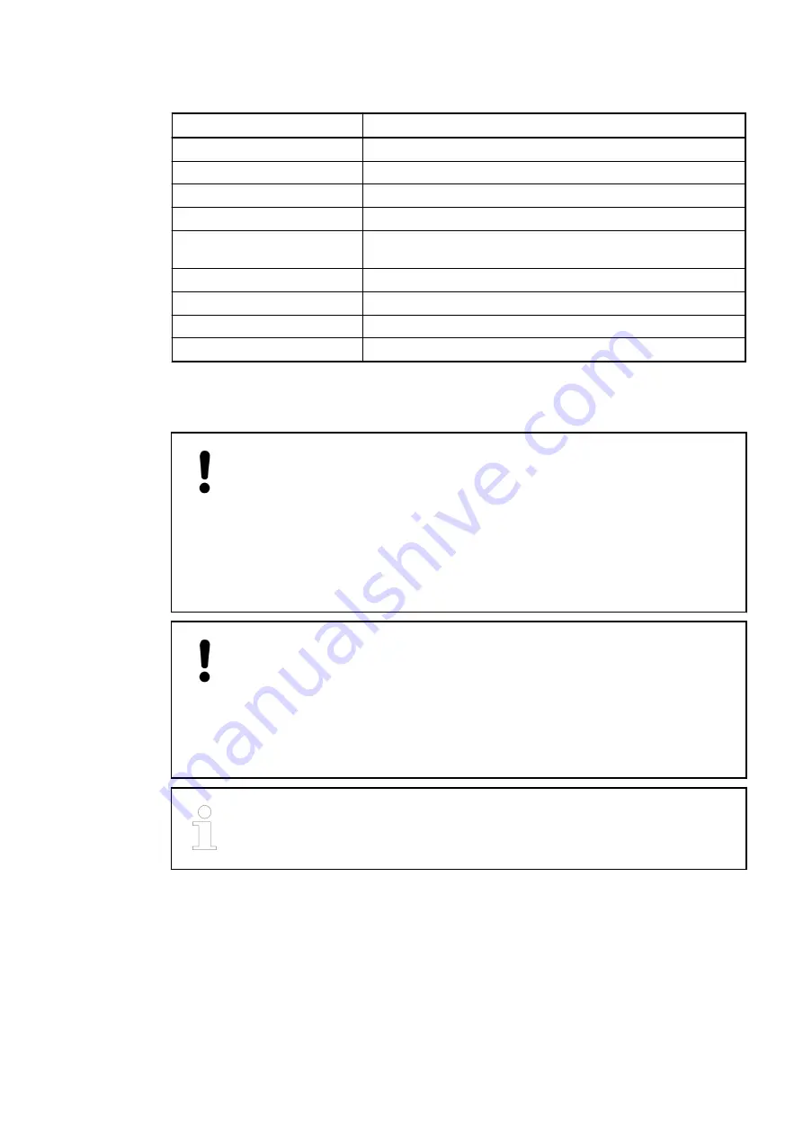
Parameter
Value
Digital inputs
8 (24 VDC), can be used as source inputs or as sink inputs
Interrupt inputs
4 (DI0...DI3), configurable
Interrupt response time
Max. 0.8 ms when input delay is set to 0.1 ms
Fast counter
2 (DI0 and DI1), configurable
Digital outputs
6 transistor outputs (24 VDC, 0.5 A max.) or relay outputs (2 A
max.), (depending on processor module)
PWM outputs
2 (DO2 and DO3), configurable
LED displays
For signal states
Internal power supply
Via processor module
External power supply
Via UP and ZP terminal
1.2.1.2.3 Electrical Connection
NOTICE!
Risk of damaging the PLC modules!
The PLC modules must not be removed while the plant is connected to a power
supply.
Make sure that all voltage sources (supply and process voltage) are switched
off before you
–
connect or disconnect any signal or terminal block
–
remove or replace a module.
NOTICE!
Risk of damaging the PLC modules!
Overvoltages and short circuits might damage the PLC modules.
–
Make sure that all voltage sources (supply and process voltage) are
switched off before you begin with operations at the system.
–
Never connect any voltages or signals to reserved terminals (marked with
---). Reserved terminals may carry internal voltages.
When replacing a processor module, it is recommended to mark each wire con-
nected to the onboard I/O terminal block before disconnecting it. This should
make sure that the wires can be reconnected in the same order.
The electrical connection is carried out by using a non-removable 20-pin terminal block.
The following block diagram shows the internal structure of the onboard I/Os:
Device Specifications
Processor Modules > AC500-eCo
2019/04/17
3ADR010121, 13, en_US
39