Solares
TM
Smart Spa Parts Manual
CD0039
15
Rev:1121
17.
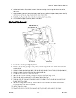
Assemble the white adjustment stop onto the cartridge so that the stop hits the left side of the
black standoffs.
18.
Line up the brass knob with the inside shape of the white stop and insert it. Avoid turning the
Rada knob any more than necessary while doing this.
19.
Watch the water temperature for a good 15-
20 seconds to make sure the temperature doesn’t
go above 105°f.
20.
Once
the valve is set you can hit the “max water temp” button again to turn off the water.
21.
Place the black cap on top of the Rada valve and hold it just far enough away to prevent the
teeth from interlocking.
22.
Rotate the cap clockwise until you hit a stop.
23.
Push the black cap in to interlock the teeth and replace the two white clips you removed earlier.
The nubs should be positioned toward the opposite clip to secure them in place.
24.
Place the screw you removed earlier into the brass adjustment knob and tighten it down.
25.
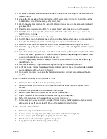
Place the large pulley back on the brass knob ensuring you get the timing belt on both pulleys as
you go.
26.
If you loosened the adjacent plate earlier then you’ll need to pull that plate away from the Rada
until the time belt is good and tight. With force still applied to the plate tighten the two screws
down on its back side to secure it into that position.
27.
Turn the large pulley counterclockwise
just past the point in which the inductive sensor’s light
(part #5) turns on.
28.
Use 2mm hex wrench to tighten set screw good in snug to lock pulley in position.
29.
Verify that pulley rotates clockwise without a problem and trips the sensor when rotating back
counterclockwise without having to force it.
30.
Go to water control screen and verify that system maintains correct temperature without a
problem.
Part # 5
–
Inductive Proximity Sensor; NO PNP; 1.5mm
1.
Disconnect M8 cable from inductive proximity sensor.
2.
Loosen top screw on inductive sensor bracket with an hex wrench and slide sensor out of
bracket.
3.
Spin large pulley on Rada counterclockwise until it stops.
4.
Slide the new sensor into the bracket and connect the M8 cable.
5.
Adjust the sensor in until it senses the screw sticking out of the pulley.
6.
Tighten the top screw on the sensor bracket until sensor is snug.
7.
Rotate large pulley back and forth a couple of times to
verify that it’s picked up by the sensor
without any issues. If sensor doesn’t light up then adjust it in a tad further.
Part # 6
–
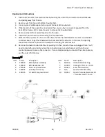
Nema 17 Stepper Motor
1.
Disconnect stepper motor from M12 cable.
2.
Remove screws securing plate (part #7 (x2)) and free motor from timing belt.
3.
Remove screws (part #8 (x4)) securing stepper motor to plate.
4.
Attach motor as shown in drawing above using screws.
5.
Reapply timing belt so that it bridges both pulleys.


