34
| DETAILED OPERATING INSTRUCTIONS
PDM
PDM Operator's Manual Version 2.4a • September 2019
GPIO Menu (General Purpose Input/Output)
If your
Information
screen shows an IP address of
0.0.0.0
and DHCP has been se-
lected, it is likely the router isn’t supplying a valid address. Power cycling PDM may be
necessary to activate DHCP. In some cases you may need to power cycle or reset the
router as well. Note that router resets can temporarily disrupt the entire data network.
PDM’s Network Time Protocol system will also report potential network issues while it
is establishing a connection with the time server. These messages appear on the
information screen, and are described on
page 30.
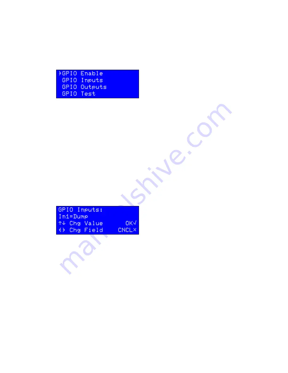
GPIO Menu (General Purpose Input/Output)
}GPIO Enable
GPIO Inputs
GPIO Outputs
GPIO Test
This menu lets you program the parallel inputs and outputs for remote control.
GPIO Enable
Select
Enabled
to activate General Purpose Input / Output
control, a parallel remote control mode accessed through the female DB-25 jack on the
rear panel. Select
Disabled
if you have a remote connected to this jack but want to
temporarily turn it off.
GPIO wiring connections are through a rear-panel DB-25 jack; details are covered on
page 53
. GPIO can also be connected directly to consoles and nodes through Livewire, if
you have the proper hardware; details are on page 59.
PDM’s GPIO system doesn’t use noisy relays and won’t be tripped by normal static im-
pulses. You can leave it
Enabled
even if there is no remote control plugged in.
GPIO Inputs
and
GPIO Outputs
The GPIO system has to be configured to determine which PDM functions appear at
which pins on the rear-panel DB-25 jack. To configure GPIO, use
¨
or
Î
to select
Ins
or
Outs
and press
√
. The LCD will look like this:
GPIO Inputs:
In1=Dump
“‘ Chg Value OK√
{} Chg Field CNCL#
Each of the 8 Inputs or outputs (e.g.,
In1
,
In2
,
Out1
,
Out2
, etc) can be assigned to a
PDM function, as listed on the following chart. The same function can be assigned to
multiple inputs or outputs, if you require two or more isolated circuits for it.
GPIO
FUNCTION
INPUT SETTING
*
OUTPUT SETTING
†
Nothing Assigned
None
None
Build button
Build
BuildTrig
This menu lets you program the parallel inputs and outputs for remote control.
GPIO Enable
Select
Enabled
to activate General Purpose Input / Output control, a paral-
lel remote control mode accessed through the female DB-25 jack on the rear panel. Select
Disabled
if you have a remote connected to this jack but want to temporarily turn it off.
GPIO wiring connections are through a rear-panel DB-25 jack; details are covered on
page 65
.
GPIO can also be connected directly to consoles and nodes through Livewire, if you have
the proper hardware; details are on page 59.
PDM’s GPIO system doesn’t use noisy relays and won’t be tripped by normal static impulses.
You can leave it
Enabled
even if there is no remote control plugged in.
GPIO Inputs
and
GPIO Outputs
The GPIO system has to be configured to determine which PDM functions appear at which
pins on the rear-panel DB-25 jack. To configure GPIO, use
¨
or
Î
to select
Ins
or
Outs
and
press
√
. The LCD will look like this:
If your
Information
screen shows an IP address of
0.0.0.0
and DHCP has been se-
lected, it is likely the router isn’t supplying a valid address. Power cycling PDM may be
necessary to activate DHCP. In some cases you may need to power cycle or reset the
router as well. Note that router resets can temporarily disrupt the entire data network.
PDM’s Network Time Protocol system will also report potential network issues while it
is establishing a connection with the time server. These messages appear on the
information screen, and are described on
page 30.
GPIO Menu (General Purpose Input/Output)
}GPIO Enable
GPIO Inputs
GPIO Outputs
GPIO Test
This menu lets you program the parallel inputs and outputs for remote control.
GPIO Enable
Select
Enabled
to activate General Purpose Input / Output
control, a parallel remote control mode accessed through the female DB-25 jack on the
rear panel. Select
Disabled
if you have a remote connected to this jack but want to
temporarily turn it off.
GPIO wiring connections are through a rear-panel DB-25 jack; details are covered on
page 53
. GPIO can also be connected directly to consoles and nodes through Livewire, if
you have the proper hardware; details are on page 59.
PDM’s GPIO system doesn’t use noisy relays and won’t be tripped by normal static im-
pulses. You can leave it
Enabled
even if there is no remote control plugged in.
GPIO Inputs
and
GPIO Outputs
The GPIO system has to be configured to determine which PDM functions appear at
which pins on the rear-panel DB-25 jack. To configure GPIO, use
¨
or
Î
to select
Ins
or
Outs
and press
√
. The LCD will look like this:
GPIO Inputs:
In1=Dump
“‘ Chg Value OK√
{} Chg Field CNCL#
Each of the 8 Inputs or outputs (e.g.,
In1
,
In2
,
Out1
,
Out2
, etc) can be assigned to a
PDM function, as listed on the following chart. The same function can be assigned to
multiple inputs or outputs, if you require two or more isolated circuits for it.
GPIO
FUNCTION
INPUT SETTING
*
OUTPUT SETTING
†
Nothing Assigned
None
None
Build button
Build
BuildTrig
Each of the 8 Inputs or outputs (e.g.,
In1
,
In2
,
Out1
,
Out2
, etc) can be assigned to a PDM
function, as listed on the following chart. The same function can be assigned to multiple
inputs or outputs, if you require two or more isolated circuits for it.
Summary of Contents for PDM
Page 78: ......


