background image

20

 | OPERATING MODES

PDM

PDM Operator's Manual  Version 2.4a • September 2019

Note that PDM is still recording during Compressed Roll Out, so there’s a possibility 

that anything talent says after the segment is “over” might get passed to the transmitter. 

Pressing 

BYPASS

 instantly switches PDM’s output to real-time and erases PDM’s memory.  

That’s why you want to press it right after talent’s last word reaches the output.

Exit by Crashing Out

This instantly switches PDM to real-time mode, and empties its delay memory.


n

Just press the 

BYPASS

 button. 

Alternate Build Modes 

You can choose how PDM will build up its delay, depending on programming needs and 

how you like working. This choice can be made or changed at any time by using the menu 

on 

page 29

.

The two other modes are Build with Insert, and Build with PreRoll

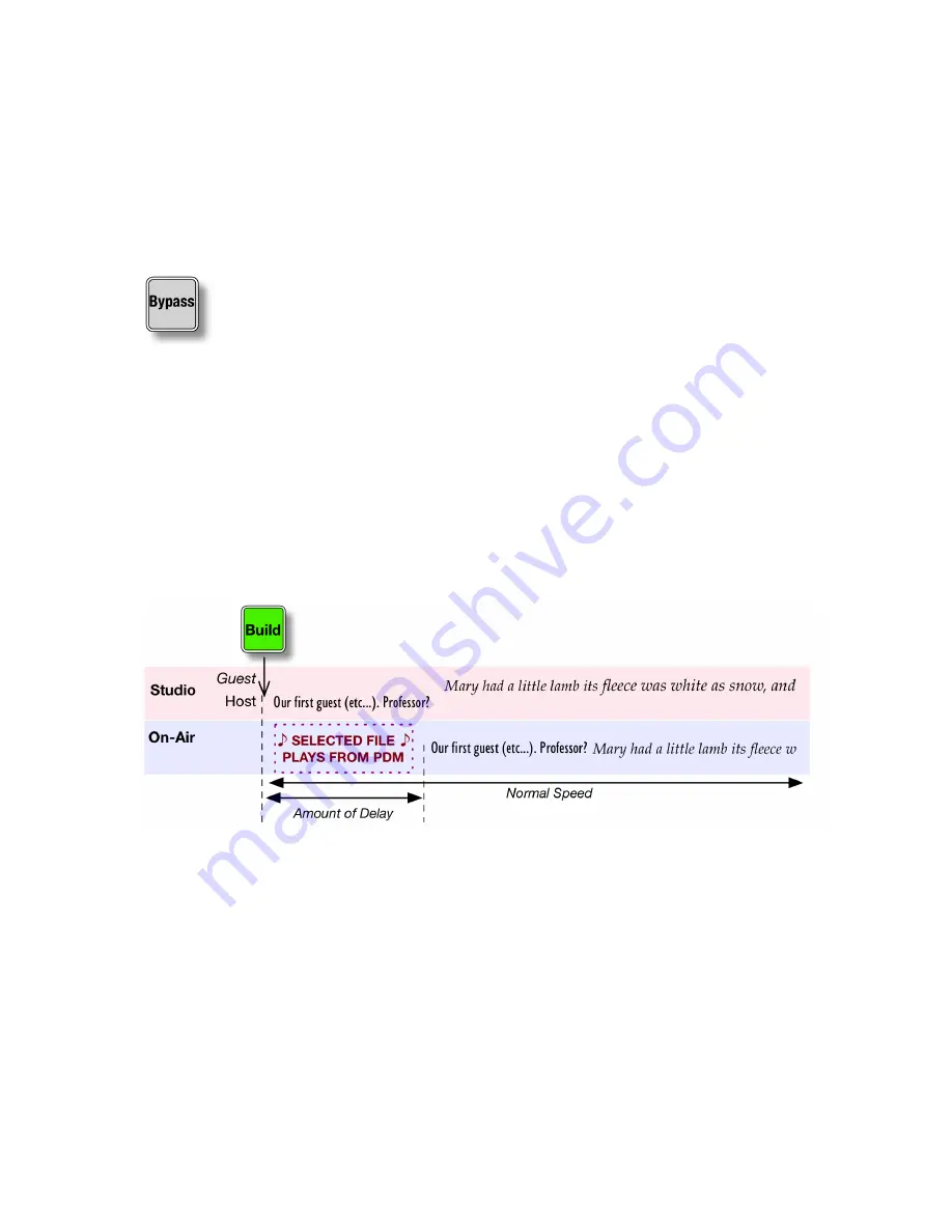
Build by Inserting an audio file

Set  

Build Mode

  to  

Insert

. Then when you press 

BUILD

, PDM will play a preset audio file 

from its internal audio storage. Meanwhile, talent starts talking and the studio signal is sent 

to PDM’s delay memory. 
When the audio file finishes playing, PDM plays delayed audio. You can now use 

DUMP

 as 

needed.
You can upload the audio files PDM uses from any computer on your network. See 

page 52

.

PDM can hold multiple Build files. You can have different ones for different programs, and 

select which one will get played from PDM’s front panel or a computer. See 

page 27

.

If the selected Build file is exactly as long as the selected 

Delay


Size

, PDM will smoothly 

join delayed audio at normal speed when the file finishes playing. 


n

If the file isn’t the same length as the 

Delay


Size

, PDM will still join delayed audio 

when the file finishes. But it will subtly speed up or slow down the output as needed, 

to achieve the preset Delay.

Summary of Contents for PDM

Page 1: ...rofanity Delay Reinvented Operator s Manual Version 2 4a September 2019 p n 2001 00350 000 Program Delay Manager AES p n 2001 00351 000 Program Delay Manager LIVEWIRE PROGRAM DELAY MANAGER TelosAlliance com ...

Page 2: ...roblems of radio broadcasters networks and content providers The company was launched in 2003 by a group of veteran broadcasters with extensive audio experience and a significant portfolio of intellectual property 25 Seven joined The Telos Alliance in 2012 Its products are designed and built in the United States 25 Seven Systems The Telos Alliance 1241 Superior Ave Cleveland OH 44114 USA 1 216 241...

Page 3: ... is the primary disconnect device To prevent risk of electric shock disconnect power cord before servicing The outlet to which this equipment is connected must be installed near the equipment and must always be readily accessible The unit should not be positioned such that access to the power cord is impaired If the unit is incorporated into a rack an easily accessible safety disconnect device sho...

Page 4: ...his document and its content are copyrighted by 25 Seven and TLS Corporation and may not be copied reproduced or distributed in any form without expressed written permission Certain libraries are licensed to You under the terms of the GNU General Public License Version 2 GNU GPL Telos is not allowed to sub license these libraries to You as You are deemed to have Your own direct license from the or...

Page 5: ...ory service We will need your unit s serial number located on the back of the unit We will issue a return authorization number which must be written on the exterior of your shipping container Please do not include cables or accessories unless specifically requested by the Technical Support Engineer Be sure to adequately insure your shipment for its replacement value Packages without proper authori...

Page 6: ...ulti tasking 10 Operating Modes 11 Build by Expanding then Dump 12 Cough Mode 13 Exit Modes 13 Alternate Build Modes 15 Delay times and speed selections 17 Front Panel 17 Detailed Operating Instructions 18 General menu procedures 19 PDM s Front Panel Menus 20 GUI andWeb Remote Control 31 Logging in to PDM from a Connected Computer 31 The PD Alert System 38 ...

Page 7: ...e Troubleshooting 62 Serial Parallel Remote control 45 Software Updates and Factory Access 63 Audio Specifications 64 Warranty 63 Close ups Some parts of this manual explain how Program Delay Manager works under the hood You don t need to read these sections to operate or install the system but they re interesting and understanding them will help you use the system better ...

Page 8: ...gram Delay Manager combines the functions of the best delay units with some unique and potentially vital features Automatic audio logging of every Dump event n n What gets fed to the transmitter is automatically recorded on a time stamped audio file There s no question of what actually went on air n n What got dumped is also automatically recorded on a time stamped off air audio file There can t b...

Page 9: ...Seven s ground breaking Audio Time Manager n n Stereo processing with CD quality even during time manipulation It s clean enough that you can use obscenity protection on live music programs and other events n n Easy operation from the front panel wired remote producer s computer or Axia console n n Total flexibility PDM can build delays without using filler material by seamlessly stretching live a...

Page 10: ...ration and control from any browser No need to navigate through menus Use PDM s graphic user interface from any computer on your local or wide area data network n n Flexible audio configuration n n XLR version includes separate stereo analog and AES EBU inputs and outputs n n Livewire version for flexible audio over IP installation in an Axia environment n n Flexible remote control n n Use GPIO bu...

Page 11: ...ll light The delay memory can hold more audio than is needed for a single Dump event When it reaches a limit you ve previously set1 the BUILD button s light stops flashing The DUMP button remains lit You can choose how long PDM takes to build a delay Choose a setting based on how quickly your talent talks how subtle you want the time manipulations to be slower speaking styles can work with higher ...

Page 12: ...a chance to store n n The size of each Dump event is determined when the unit is set up but can be changed at any time even while you re on the air n n When there s enough audio in memory to smoothly Dump the full amount you ve preset the DUMP button will light7 This starts a few seconds after you begin a segment or as you rebuild after an earlier Dump event n n You can also press DUMP when it s n...

Page 13: ...e for example if you want an 8 second delay create an 8 second file of replacement audio After the file finishes playing PDM s output switches back to delayed audio To dump a longer comment tap the DUMP button again while PDM is dumping Each time you do PDM will add the preset Dump Size s seconds to the current Dump event For example if you ve set a Dump Size of 4 seconds tapping twice will dump 8...

Page 14: ... more seconds than are stored in memory PDM will mute the output It will also flash the COUGH button to warn you of dead air Multi tasking Whenever you press the DUMP button program audio gets dumped as you d expect But PDM also does other things when you press that button a PDM starts writing a pair of audio files one of what was broadcast and one off air of what actually took place in the studio...

Page 15: ...he LCD will look like this Exiting Speed 10 Delay 3 4s Menu When Delay equals 0 seconds PDM exits Delay mode feeding the input signal to its output Operating Modes A visual note PDM is an advanced time manipulation tool for radio broadcasters But since we can t play audio in this manual we ll use graphics to explain how PDM operates These drawings might also help you visualize what PDM is doing wh...

Page 16: ...uilt up to cover the gap during a Dump event There are other ways to build delay shown on page 20 n n Talent starts the program at the usual time presses the BUILD button and starts talking PDM will subtly slow down9 the signal it sends to the transmitter shown in red while storing the real time signal in its delay memory When the delay memory reaches a pre set limit PDM s output returns to normal...

Page 17: ... the producer n n Talent holds the COUGH button down While it s down the delay memory stops recording and talent is heard in the control room only The audio already in memory from before COUGH was pressed still goes to the transmitter This of course empties the delay memory by the number of seconds COUGH is held down When COUGH is released PDM starts rebuilding its delay Another visual note In thi...

Page 18: ...ng an old fashioned tape delay n n Talent finishes a sentence presses EXIT and stops speaking n n PDM continues to play previously recorded material at normal speed until the delay is empty Then PDM starts passing the incoming signal with no delay n n Note that COUGH is disabled while exiting by rolling out In this mode nothing is recorded after Talent presses exit It s like Talent s mic gets turn...

Page 19: ...ve given PDM As a general guide As a general guide Speed Setting Minutes seconds to build 8 second delay 7 1 45 10 1 10 15 45 Choose a Speed appropriate for your talent s style of delivery so listeners won t notice the time compression Hosts who speak very quickly usually sound better with lower PDM Speed settings Quick Exit with Compressed Roll Out This is faster than using either Compress or Rol...

Page 20: ...ith Insert and Build with PreRoll Build by Inserting an audio file Set Build Mode to Insert Then when you press BUILD PDM will play a preset audio file from its internal audio storage Meanwhile talent starts talking and the studio signal is sent to PDM s delay memory When the audio file finishes playing PDM plays delayed audio You can now use DUMP as needed You can upload the audio files PDM uses ...

Page 21: ...ll subtly speed up or slow down the out put as needed to achieve the preset Delay Build with PreRoll You may want to build your delay without changing speed or playing an insert file Pre Roll Mode lets talent start their introduction before the scheduled program time This is often done by studios feeding a network rather than a local transmitter Set Build Mode to PreRoll Then you can press BUILD a...

Page 22: ...nergy such as musical performances or background crowds at events PDM s algorithms excel at speech and won t destroy your talents delivery Lower speed numbers cause the least amount of tempo change and are usually impercepti ble But they take longer to fill the delay memory or to return to real time Higher speed numbers fill the memory more quickly but might cause a noticeable speed change on fast...

Page 23: ...cel button exits the current menu without making any changes The BUILD EXIT COUGH and DUMP buttons are discussed starting on page 11 The BYPASS button is used for emergencies or when you want to take PDM out of the signal chain10 It connects PDM s analog and digital inputs to its outputs with no processing or delay It also clears PDM s delay memory PDM automatically goes into electrical bypass con...

Page 24: ... studio background noise with no talking or music n n As the peak input signal increases between 36 dBFS and Full Scale successive LEDs light up All four LEDs will light yellow if PDM is expecting a Livewire input but not seeing a valid signal This is usually a configuration problem All four LEDs will also light yellow in the unlikely event of internal error even on XLR analog and AES EBU systems ...

Page 25: ...modes see page 23 Press to enter the configuration menus After you turn off Bypass mode the ready screen appears This screen also appears after you exit a delay PDM is in Bypass 10 32 00a Menu This says the current time is 10 32 AM PDM can display time in 12 or 24 hour modes Press to enter the configuration menus After you turn off Bypass mode the ready screen appears This screen also appears afte...

Page 26: ...wing PDM will start building a delay General menu procedures A few elements are common to many of PDM s screens Menu means press to see a deeper menu See PDM s Menus below OK means press to apply a parameter change and return to the next higher menu But it won t be saved permanently within PDM See Confirming Changes below CNCL means press to return to the next higher menu without making any addi t...

Page 27: ...r via its secure Web interface For this part of the manual we ll show the LCD versions If you re controlling PDM from a Web browser most of the GUI versions of the menus will be virtually identical The Web interface also includes extra configuration options that aren t available from the front panel These start on page 31 Master menu If you press while menu is displayed the screen will change to l...

Page 28: ...e dBu an analog measurement with digital dBFS Analog dBu is a comparison to an arbitrary voltage 775 v and signals can be much hotter A console s output is typically 4 dBu 1 228 v when the meter reads 0 VU but that s for a sinewave test signal Peaks in voice waveforms in real world broadcasting can sometimes be considerably above that even though properly calibrated VU meters are deliberately too ...

Page 29: ...Exiting or Full Max Delay Use and Î to set a limit up to 99 seconds for the Delay Size func tion noted immediately above This is to prevent operators from accidentally setting unrealistic delays Controls menu options Dump Size Displays a screen of Dump Seconds in 1 second increments Use and Î to select how much programming PDM will delete when you press the Dump button Choose between 1 0 and 60 0 ...

Page 30: ...tween Dump and Overkill mode n n Dump is the normal mode most people are used to it jumps ahead in time skipping the objectionable audio It then rebuilds PDM s delay automatically as needed n n Overkill plays a pre selected file instead of the objectionable audio The delay is maintained and doesn t have to be rebuilt Overkill File This menu lets you choose which audio file previously uploaded to P...

Page 31: ...orized access via the net work They are visible from PDM s front panel menus Note In previous PDM software the System Menu also included RS 232 and External Clock Offset These functions now appear only on the Web interface page 35 System menu options Brightness Select a value for the LCD display Contrast Select a value for the LCD display Time Zone Select a time zone when Network Time Protocol a f...

Page 32: ... appropriate settings for your data network 2 Menu may be slightly different for Livewire equipped PDMs See page 68 Network menu options DHCP Choose enabled or disabled Use Enable if your network router is set up for DHCP address assignment When DHCP is enabled your unit s IP address Subnet DNS Server and Gateway are supplied by the router Enabled is the factory default n n Disabling pressing DONE...

Page 33: ...ute of Standards and Technology s website16 International time server domain names are listed at www ntp org Please respect the access policies listed by the server provider and IT department PDM users should never select a Primary server for NTP updating use Pool or Secon dary servers instead The best way we have found to test whether NTP services are working is to manually offset your PDM clock ...

Page 34: ...jack details are covered on page 65 GPIO can also be connected directly to consoles and nodes through Livewire if you have the proper hardware details are on page 59 PDM s GPIO system doesn t use noisy relays and won t be tripped by normal static impulses You can leave it Enabled even if there is no remote control plugged in GPIO Inputs and GPIO Outputs The GPIO system has to be configured to dete...

Page 35: ...ss Cue point 1 Cue1 Cue1 Cue point 2 Cue2 Cue2 etc up to 8 Cue points etc etc Flag point 1 Flag1 Flag2 Flag point 2 Flag2 Flag2 etc up to 8 Flag points etc etc Pause temporarily suspend delay build Pause Utility point 1f Util1 Util1 Utility point 2f Util2 Util2 etc up to 4 Util points etc etc Delay memory pulse on Full FullTrig Delay memory pulse on Empty EmptyTrig Build mimic lamp state BuildLamp...

Page 36: ... range from 100 to 1000 ms and can be set in the Configuration page Hardware GPIO Section Default value is 250 ms n n If an output setting ends with Lamp PDM s GPIO output mimics the front panel button s lamp It stays low when the lamp is on high when the lamp is off and cycles when the lamp is flashing This can be handy for building custom remotes for talent and producers n n Building Exiting Del...

Page 37: ...hey re reached n n For example if the network provides a contact closure when it s time for a local break connect it to an input that has Cue1 assigned No matter how much delay is applied PDM will generate a Cue1 output when that sample is reached which you can use to trigger other equipment to play the break n n Flag marks record a continuous logic input Their output reflects that logic state whe...

Page 38: ...nt panel firmware and system software You ll need this information if you call 25 Seven for support The NTP Status display shows one of three messages indicating the current connection with a remote time server n n Search PDM is seeking a path to the remote NTP server If this message persists it may indicate that the NTP server address you entered isn t valid n n Query PDM has contacted the remote...

Page 39: ...ng PDM will draw its Graphical User Interface on your Browser s screen Port Forwarding GUI Communication PDM s web server connects at http port 80 Once you log in and the front panel or configu ration pages are loaded embedded Adobe Flash movies in our GUI let your browser control the PDM via port 5444 Both these ports must be open and available for the GUI to function If you are trying to connect...

Page 40: ...he IP address and that port number such as 10 11 12 100 82 You should see a pattern here Ports 80 and 5444 are paired When inbound browser traffic comes in at port x the Flash movie control port will automatically be set to x 80 5444 You don t need to specify Flash ports just which port your router uses to talk to PDM if you set that and associated firewall permissions properly at the router our s...

Page 41: ...ately 720 x 330 pixels When using the GUI to control a PDM in another studio always check to make sure the unit isn t in use Remember a remotely controlled PDM in Ready mode may actually be feeding audio to your program bus Changing its settings remotely might disrupt programming This page is fully interactive On screen buttons can be clicked with your mouse the text displays whatever is on PDM s ...

Page 42: ...ultaneously from the same computer All you need to know is each unit s IP address its user name and its password page 39 n n Log in to any connected PDM and click the second link at the bottom of the FRONT PANEL screen on the GUI Click here to open multiple front panel windows n n Another Browser tab will appear with a dialog where you can enter the IP address of any other PDM accessible to your n...

Page 43: ...u can identify specific units These small front panels are displayed in the order you entered them To change their order or delete particular machines n n close the multi PDM Window in your browser n n click multiple front panel windows again n n enter desired addresses in the new order Up to 20 PDM front panels can be displayed and controlled simultaneously in a single browser window ...

Page 44: ...tion page Click on the CONFIGURATION tab at the top of the GUI and your browser changes to look like this P r ogr a m D e la y Ma n a ge r P D M1 FRONT PANEL CONFIGURATION PD ALERTS DUMP ARCHIVE AUDIO FILES INFORMATION Top part of Configuration page there s more on the next page of this manual ...

Page 45: ...2 4a September 2019 Bottom part of Configuration page continued from previous picture PDMs with Axia Livewire software will have a few additional entries see page 71 Changes that you enter on this page don t take effect until you press the Save button on the bottom ...

Page 46: ...0 and 1000 ms This is useful when connecting to some older equipment requiring longer pulse inputs Factory Default is 250 ms Delayed Data Streams lets you keep Program Associated Data and text or automation cues in sync with the audio at all times Two separate simultaneous streams are supported and there are flexible options for sources and outputs They re discussed fully on page 61 Other I O lets...

Page 47: ... a change is pending and the Save and Revert buttons will flash n n When you successfully Save those changes the selection title reverts to normal text The Save and Revert buttons stop flashing and a confirmation dialog appears on screen You must click OK on this dialog before you can make other changes n n If you type an invalid value or setting that field appears in red to indicate an error The ...

Page 48: ...Usually five or six seconds is plenty but if you are running very long program delays set context to the maximum value PD Alert attached audio e mails Enter the e mail addresses of people or servers who should receive PD Alerts with attached audio files Use the PD Alert text field below for users who don t want to receive audio files Those users can still access audio files from within PDM n n If ...

Page 49: ...DM will automatically delete dump files as they reach that age Test PD Alerts After you ve entered e mail addresses use this feature to verify that PDM is set up properly A test message will be sent to the addresses in both PD Alert e mails fields n n If one of the e mail addresses is invalid22 your ISP will relay an error message You can check for these messages by logging into the mail account y...

Page 50: ...roblem Log File Lock Box Files generated by the PD Alert system can be copied to your computer and from there can be saved forwarded or deleted like any other computer file Dump files in PDM s internal storage cannot be edited or deleted manually That s for security There is no command to do this either in the GUI or on PDM s front panel n Dumped files stick around as long as possible until PDM s ...

Page 51: ...ions running very long delays log file audio will start with the pre context audio plus as much of the delay buffer as will fit in the remaining seconds What Gets Saved For each Dump event PDM saves separate OnAir and OffAir audio files Each pair is kept as full resolution wav for highest quality even though you can choose to have it compressed before being e mailed Both files include a few second...

Page 52: ...or Overkill Dump Mode From this page you can Delete Rename or Upload files File names are links to the actual file so you can listen to the files by clicking their names The file pdm_demo_insert wav is included for testing and doesn t have Delete or Rename buttons 25 OnAir files are an exact copy of what gets sent to the transmitter So if PDM was slowing down the audio after a dump to rebuild a de...

Page 53: ...with digital audio through its AES EBU connection it will run at that audio s sample rate This happens even if you re processing signals from the analog inputs to keep the AES EBU outputs synchronized with the rest of your studio If you re using Livewire files should be Axia s native sample rate of 48 kHz n n Maximum Insert file length is 6MB about 35 seconds of audio at 44 1 kHz n n PDM can store...

Page 54: ...n settings audio networking and time format along with the internal temperature and 25 Seven s identification numbers Note that these settings may be changed only from the PDM front panel not via the config uration page The page does not update automatically refresh your browser if you need to see recent changes Information page It s a single tall column on your screen shown as two pieces here to ...

Page 55: ...work Web browser or both at the same time The comprehensive language uses abbreviations to query delay depth and internal tem perature access all GPIO functions and continuously report PDM s operating status Standard serial or IP based connections Data and control lines appear on a male DB 25 connector in both RS 232 and RS 485 formats as well as over a network Enable RS 232 and set its protocols ...

Page 56: ...n custom serial in terfaces to other equipment Use the enable command page 59 to specify which events generate a message Request syntax Requests consist of a command something for PDM to do usually followed by arguments what it should act on and then the LF Commands include down Start the event described by argument up End the event described by argument trigger Momentary activation of argument sa...

Page 57: ... temperature in whole degrees Celsius or Fahrenheit depending on the request Output Event messages sent by PDM are NameOfEvent 1 or 0 followed by LF NameOfEvent can be any event reported by the GPIO If an event is momentary such as a button press the Boolean does not appear 1 or 0 appear only if the event is an ongoing state such as whether the system is currently in Bypass Mode These numbers do n...

Page 58: ...Trig 1 Exit completed Empty trigger asserted DelaySafe 1 Dump increment achieved delay is now safe Bypass 0 PDM removed from Bypass mode DUMP GUEST LF unknown command DUMP LF PDM doesn t understand this instruc tion so no action is taken Help does not require an argument n n If you send help LF by itself it returns a list of valid commands n n If you specify any command as the argument it returns ...

Page 59: ...m enable EventName LF where EventName is a change in PDM s current status For example enable DumpTrig LF tells PDM to send a message whenever DUMP has been activated n n You can put two or more EventNames in the same enable command Separate them by spaces For example enable DumpTrig Muted LF tells PDM to report any time either DUMP or MUTE has been activated n n Use All for EventName as a shortcut...

Page 60: ...p DUMP button is flashing CoughLamp COUGH button is flashing All Enables event reporting for all of the above Lamp functions mimic the lamp state and report 1 or 0 every time a front panel button flashes on or off disable This command turns off reporting of one or more output events It follows similar syntax n n disable DumpTrig LF tells PDM to stop reporting that DUMP has been activated n n disab...

Page 61: ...an function as client or server You can mix these types for maximum flexibility These choices all appear on the configuration page in the Delayed Data Streams section page 46 Only one input can feed data at a time but multiple devices can be listening to delayed data on the outputs Two drop down menus lets you choose the stream inputs n n Select Disabled RS 232 port Local network port 5445 for Str...

Page 62: ...at dust hasn t built up The internal power supply will self adapt to any voltage between 100 240 v 50 60 Hz It consumes 1 8 A maximum typical draw is about 32 watt 120VAC We recommend that PDM be connected to a UPS uninterruptible power supply to prevent loss of audio in case of a power disruption This is good advice for any mission critical electrical device XLR versions of PDM are normally fed b...

Page 63: ...EC 958 Professional 5v p p 110Ω balanced on XLR connectors When set to s pdif the voltage and impedance switches to IEC 958 Consumer 5v p p 75Ω unbalanced connect signal to pin 2 and shield to pins 1 and 3 The digital input jack on XLR equipped PDMs is active at all times even if you ve selected analog for the audio input This provides the most flexible operation But it can have unexpected effects...

Page 64: ... to pin 2 and shield to pin 3 only Do not connect pin 1 for s pdif operation If there is no signal on the digital input jack PDM provides its own low jitter clock at a 44 1 kHz sample rate When there is a valid 44 1 or 48 kHz signal at the digital input jack even if analog inputs are selected the internal clock and digital output are locked to it But see the warning about digital clocking above An...

Page 65: ...000ms adjustable on the configuration screen Factory default is 250ms The 5v supply can provide 200 mA more than adequate for 8 LEDs and 8 logic inputs Total draw should not exceed this value This supply is protected by an internal self resetting thermal circuit breaker If this breaker should trip power off and allow several minutes for it to reset Basic remote control 1 Use the connections shown ...

Page 66: ...xternal logic or relay circuits PDM s GPIO inputs and outputs are isolated from its power supply and ground and can be connected to external logic circuits or the power supplies in remote equipment n n Inputs require at least 6 mA flowing from the input common pin 13 and the individual input circuit pin n n Outputs can carry up to 25 mA up to 30 V DC per channel between the individual output circu...

Page 67: ...on the same RS 232 connector as it s received so if you have one device generating data and another one listening you ll need a Y cable to split the TX and RX signals RS 485 There are also two independent RS 485 differential data lines on this connector Each is independently controlled and programmable as input output or bi directional Serial Pinouts on DB 25 PIN SIGNAL 1 NC 2 RS 232 TX Output fro...

Page 68: ...o understand Livewire specific setups If you have an analog AES EBU version of PDM and wish to convert it to run as a Livewire device please contact customer support Network Setup Since PDM Livewire uses network connections instead of standard analog or digital audio wiring it won t operate until it s been properly configured for your network PDM s output audio is broadcast to the network as a sin...

Page 69: ...Address and Subnet Mask according to the instructions on page 25 You may need to contact your network administrator or Axia instructions for specific information Save the changes and power cycle PDM so they get ap plied Once you ve done this setup view the INFORMATION page to verify PDM s IP address Then you can check the connection by Pinging37 that address from another computer on your network I...

Page 70: ... it a channel number in the Axia Source screen Other devices will be able to hear PDM s output by using this channel number as an assigned Destination signal Select Axia Src Ch from the Axia menu The LCD will look like this Remember on the Axia Dest screen you decide which signal this PDM is the destination for Enter the channel number of some other source on the network PDM will treat that source...

Page 71: ... the CONFIGURATION tab In addition to the functions described on page 44 Axia equipped PDMs have the options in the following screenshot Ports 3 and 4 not shown offer the same drop down menus as Ports 1 and 2 PDM provides four Livewire ports with five lines each of user selected input and output control n n Each port s section contains a Port Address entry line Type the address of a Livewire devic...

Page 72: ...e web browser enter the IP address of this particular console This will take you to the Element Control Center page 2 In the left hand column under Sources Profiles select Configuration A new page appears which contains a list of your Show Profiles 3 Select your current Show Profile from the list A page listing the Show Profile s configuration sections will appear 4 Select Monitor section A page a...

Page 73: ...input 1 low on DB 15 number 4 Port 4 on that node PDM goes into Dump mode Of course you re free to use any input or output on any port of any node on the network and assign any PDM function About the Bypass button In standard XLR analog digital versions of PDM the Bypass button takes PDM out of the signal chain Hardware relays connect PDM s analog and digital inputs to its outputs with no processi...

Page 74: ... within Pathfinder The screen will go away after PDM has successfully logged onto the Livewire network Once it is gone PDM s LED level meter should switch from yellow to green You should see the meter bounce when IP audio is being properly sent to PDM If the Audio stream message remains up for several minutes after you start PDM check the following n n Does the INFO screen show a valid IP address ...

Page 75: ... sure PDM is in Bypass mode before beginning any software update Remote factory access We have also provided a unique way for our software engineers to perform remote diagnos tics if there are ever any problems You have to specifically set up Remote Access before we can start This setup has to be done before each Remote Access session We absolutely can t get into your PDM unless you let us The set...

Page 76: ... 2019 Audio Specifications S N 84 dB with 10 dB headroom 94 dB dynamic range A weighted THD 1 kHz 025 IMD IHF 05 Frequency response 5 dB 20 Hz 20 kHz Measured in all modes using analog connections expect even better results with digital input and output ...

Page 77: ... 77 PDM PDM Operator s Manual Version 2 4a September 2019 Warranty Telos Alliance LimitedWarranty For the latest Telos Alliance warranty visit telosalliance com warranty ...

Page 78: ......

Page 79: ...uperior Avenue Cleveland OH 44114 USA Main office 1 216 241 7225 24 7 Tech Support 1 216 622 0247 Fax 1 216 241 4103 telosalliance com 2019 TLS Corp The Telos Alliance All Rights Reserved C19 14012 PN 1490 00091 003 PDM CD OWNER S MANUAL ...

Reviews: