|
25
PDM
PDM Operator's Manual Version 2.4a • September 2019
Detailed Operating Instructions
When PDM is first powered up, transport buttons will light, and the unit will be in Bypass
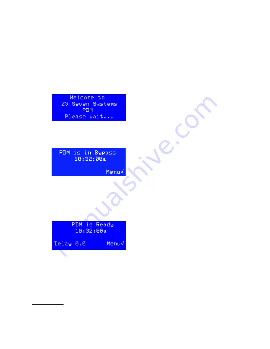
mode. After about 10 seconds, the LCD displays this initialization screen for a few moments:
The
BYPASS
button is used for emergencies or when you want to take PDM out of the
signal chain
1
. It connects PDM’s analog and digital inputs to its outputs, with no proc-
essing or delay. It also clears PDM’s delay memory.
PDM automatically goes into electrical bypass, connecting its XLR inputs to its match-
ing outputs, when power is removed. Analog inputs are passed to their respective
analog output; AES/EBU input is passed directly to the AES/EBU output. This is totally
passive and no level adjustment or analog/digital conversion takes place.
Input Level Meter
PDM’s four color-coded LEDs indicate audio input level at the processor. They’re con-
nected after the analog-to-digital converter on XLR-equipped PDMs, so they can
accurately monitor any input regardless of the
Input
Sensitivity
setting.
•
If all four LEDs are dark, the input signal is below
-36 dBFS. This usually represents normal studio
background noise, with no talking or music.
•
As the peak input signal increases between
-36 dBFS and Full Scale, successive LEDs light up.
All four LEDs will light yellow if PDM is expecting a Livewire input but not seeing a valid
signal. This is usually a configuration problem. All four LEDs will also light yellow in the
unlikely event of internal error, even on XLR (analog and AES/EBU) systems.
PDM’s input meter shows instantaneous peaks as a diagnostic aid. It doesn’t display
RMS voltage or time-integrated level, and isn’t a replacement for the sophisticated
loudness meters found in a modern broadcast facility.
Detailed Operating Instructions
When PDM is first powered up, transport buttons will light, and the unit will be in By-
pass mode. After about 10 seconds, the LCD displays this initialization screen for a few
moments:
Welcome to
25 Seven Systems
PDM
Please wait...
Once the hardware is successfully initialized, the screen will update; the level meters
will show activity if there is a valid audio input. PDM stays in Bypass mode
1
, and a
screen like this appears:
1
Occasionally, you may need to do software updates or other system-level maintenance (page 56). Put the unit
in Bypass mode, or remove it from the signal chain, before beginning these operations.
Once the hardware is successfully initialized, the screen will update; the level meters will
show activity if there is a valid audio input. PDM stays in Bypass mode
11
, and a screen like
this appears:
This says the current time is 10:32 AM. PDM can display time in 12 or 24 hour modes; see
page 23.
Press ◊ to enter the configuration menus.
After you turn off Bypass mode, the “ready” screen appears. This screen also appears after
you exit a delay.
PDM is in Bypass
10:32:00a
Menu√
This says the current time is 10:32 AM. PDM can display time in 12 or 24
hour modes.
Press
◊
to enter the configuration menus.
After you turn off Bypass mode, the “ready” screen appears. This screen also appears
after you exit a delay.
PDM is Ready
10:32:00a
Delay 0.0 Menu√
This says PDM is processing audio, and delaying it by whatever amount is
displayed on the bottom line of this screen.
• When you first enter
Ready
mode, PDM has no delay. This makes the
audio transition seamless.
• If you press
BUILD
, PDM starts to add delay and this number counts up.
If you press the
BUILD
button while the main screen is showing, PDM will start building
a delay.
General menu procedures
A few elements are common to many of PDM’s screens:
Menu√
means press
◊
to see a deeper menu. See
PDM’s Menus
, below.
OK√
means press
◊
to apply a parameter change, and return to the next higher menu.
But it won’t be saved permanently within PDM. See
Confirming Changes,
below.
CNCL#
means press
˛
to return to the next higher menu without making any addi-
tional changes. If you’re on the Master menu, pressing
˛
exits the menu system and
takes you to either the Main operating screen or the Confirmation screen (next section).
“‘ Chg value
means use
¨
or
Î
to change the value highlighted on this screen
{} Chg field
appears when a screen has more than one value that can be changed.
Use
Ò
or
‰
to select which value is changed by the
¨
or
Î
buttons. The active field
will be flashing on PDM’s screen.
More“
and
More‘
mean use
¨
or
Î
to see more menu options in this category
Confirming Changes
If you’ve made any parameter changes while in the menu system, you’ll see a Confirma-
tion screen like this before you return to the Master menu
2
:
Configuration
has Changed
Save? YES√
NO
#
Press
◊
to permanently save these changes
Press
˛
to erase these changes and restore PDM’s former settings
1
You may also see a brief
Waiting
for
audio
stream
message while PDM initializes its audio hardware.
2
Depending on which menu you’re in, you may need to press
˛
a few times to see the Confirmation screen.
This says PDM is processing audio, and delaying it by whatever amount is displayed on the
bottom line of this screen.
n
When you first enter Ready mode, PDM has no delay. This makes the audio transition
seamless.
n
If you press build, PDM starts to add delay and this number counts up.
If you press the
BUILD
button while the main screen is showing, PDM will start building a delay.
11 You may also see a brief
Waiting
for
audio
stream
message while PDM initializes its audio hardware.
Summary of Contents for PDM
Page 78: ......


