STAND ALONE UNIVERSAL THERMOSTAT
The SATouch is a universal color touch screen programmable G/E or H/P thermostat, microprocessor based,
auto changeover, stand alone thermostat used to control stand alone fan coil units with the GEN II system. The
SATouch is configured for Gas/Electric (2H, 2C) with selectable fan operation. The SATouch reports the supply
and return air temperatures and has a large, easy to read display.
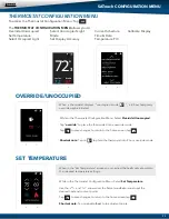
The SATouch is very easy to configure through the mobile App or by manually adjusting settings at the thermo-
stat.
The SATouch features an on board thermistor for precise temperature measurement. In the event of power loss,
the Heat and Cool set points are stored in non-volatile memory, without the need for battery backup.
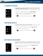
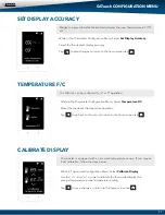
Space ambient temperature is continually displayed with large, easy-to-read numbers. SATouch temperature
display range is 47° - 95°F. Heat and Cool set points and operation modes are all indicated on the display.
Programmed set points can be manually adjusted at the thermostat or electronically locked through the mobile
app to provide limited manual set point adjustment. During unoccupied hours, temporary operation can be
overridden with a touch of a button.
Thermostat Operation
COOL - The thermostat will make a Y1 cool call when the space temperature rises 1° above set point. Y2 will
energize when the space temperature rises 2° above the cool set point or whatever the 2nd stage temperature
is set for. When the room temperature reaches set point Y1 and Y2 will de-energize. O or B energize for the
reversing valve circuit, depending on configuration. The G circuit is energized for fan.
HEAT - The thermostat will make a W1 heat call when the space temperature is 1° below the heat set point. W2
will energize when the space temperature is 2° below the heat set point or whatever the 2nd stage temperature
is set for. When the room temperature reaches set point W1 and W2 will de-energize.
Note: When the thermostat is configured for GAS operation the fan circuit is not energized in heat mode.
Note: When the thermostat is configured for ELECTRIC operation the fan circuit is energized in heat mode.
EMERGENCY HEAT - When Emergency Heat is selected in the configuration menu on the thermostat on a call
for heat, there is an output signal on “W2” for backup heat and “G” for the fan. The compressor circuits Y1
and Y2 are locked out during heat calls, until the emergency heat function has been turned off in the configu-
ration menu.
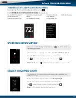
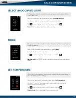
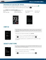
FAN MODE - Is factory set for “Auto”, to configure the thermostat to run the fan constant “On”.
Go to Thermostat
Advanced Menu, Select Fan Mode; Select the the desired fan operation “Auto” or “On”.
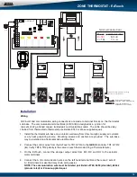
INSTALLATION
Thermostat and Terminal base
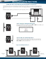
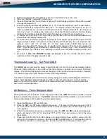
1. Install the thermostat on an interior wall, away from drafts, supply air currents and direct sunlight or any heat
generating source.
2. Remove the thermostat from its sub-base, by pulling the thermostat and sub-base appart.
3. Install the thermostat sub-base to the wall using the provided anchors and screws.
21


