34
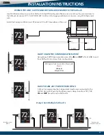
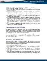
1. Determine which thermostat address is to have an additional one or two votes.
2. Place the PRIORITY jumper
(F)
on both pins.
3. Press and hold the SET and UP buttons
(H)
, and the LED display will scroll through the number
of zones starting with 01.
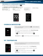
4. When the display indicates the address (01 to 17) of the thermostat you want to add votes to,
release both buttons and press the DN button. The display will scroll through 00, 01, 02. To
add one additional vote, release the DN button when the display indicates 01 (this assigns a
total of 2 votes). To increase the votes by two, press the DN button and wait until the display
indicates 02 and then release the DN button (this assigns a total of 3 votes maximum).
5. To change the votes back to a single vote, press the DN button on the selected address and
release when the display indicates 00.
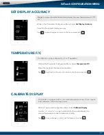
6. To review the vote status of all of the thermostats in the system, press the UP button; and the
display will first indicate the address number starting with 01and then the vote status for that
address. 00 = 1 vote 01 = 2 votes 02 = 3 votes. Upon review, if stat #1 has 2 votes, the
display will show Stat 01 followed by 02 signifying the number of Priority votes assigned to
Stat 1. Stat 02 will appear followed by a blank display, indicating only 1 vote; and Stat 03 will
appear followed by a blank screen, indicating no priority votes have been added to Stats 02 or
03.
7. Be certain to
Place the PRIORITY jumper on one pin
to put the controller back into normal
operation with the changes that were made.
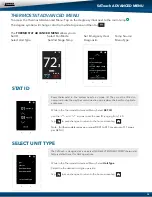
Thermostat security - Set Point LOCK
The
GEN II
system provides the ability to electronically lock all of the zone thermostats (global).
When the thermostats are in the LOCK mode, there will be a padlock icon on each thermostat
display. The LOCK mode limits the manual changing of the heat and cool set points to a maximum
of 2° above or below the initial heat and cool set point temperatures.
To set the thermostats for the LOCK mode, simply change the switch position
(K)
from UNLOCK to
LOCK. All of the thermostats will change to LOCK on the next system poll. To unlock, set the
switch to the UNLOCK position; and the thermostats will drop the icon after the next system poll
and revert to normal operation.
Air Balance - Force Dampers Open
When performing an air balance on the supply air outlets, the
GEN II
controller provides a unique
feature to simplify this procedure. The
GEN II
controller will put all thermostats in a cool call which
will open the dampers 100% and bring on the system blower.
1. Place the
EH
jumper
(F)
over both pins
2. Press the
SET
and
UP
buttons
(H)
simultaneously – This puts a global cool set point of 58°F
(14°C) on all of the zone thermostats, and the controller energizes the “G” fan output only; Y1 is
not energized.
3. When the air balance procedure is completed, press the
SET
and
DN
buttons simultaneously,
which will assign 70°F (21°C) Heat and 75°F (23°C) Cool set points on all of the zone
thermostats.
4. Press and hold the SET and DN buttons; and while holding these buttons, remove the EH
jumper tab and place it on one pin. Release the
SET
and
DN
buttons. This procedure returns
the
GEN II
controller to normal operation. For Electric Heat fan configuration, see Page 5.
ADVANCED FEATURE CONFIGURATION


