REMOTE AND AVERAGING SENSOR INSTALLATION
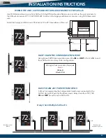
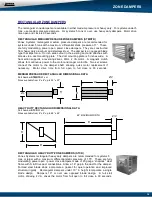
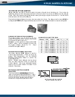
The following wiring diagram is used when remote temperature sensing is desired on a job. A Zonex Systems
EzTouch-RS is required, as is a remote sensor (part # RS). Thermostats and sensors are wired in parallel.
REMOTE SENSOR
Install thermostat per installation instructions. All remote sensors include a wiring harness. Plug wiring harness into the
back of the thermostat, this will provide two wires to connect the remote sensor to the thermostat. Per the drawing above,
wire the remote sensor in parallel, one wire from the thermostat will connect to + terminal on the sensor, the second wire
will connect to - terminal using 18AWG thermostat wire. Verify sensor operations.
31
AAA
AAA
BB
BB W1
REHEAT
AAA
AAA
BB
BB W1
REHEAT
AVG 1
AVG 2
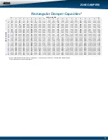
The following wiring diagram is used when temperature averaging is desired on a job. This wiring diagram is to average
two areas of a building for one thermostat. A Zonex Systems EzTouch-RS is required, as are two AVG averaging sensors
(part # AVG). Thermostats and sensors are wired in parallel.
TEMPERATURE AVERAGING
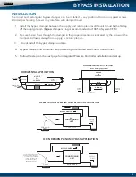
Install thermostat per installation instructions. All averaging sensors include a wiring harness. Plug wiring harness into
the back of the thermostat, this will provide two wires to connect the averaging sensor to the thermostat. Per the drawing
above, wire the AVG averaging sensor in parallel, one wire from the thermostat will connect to + terminal on the sensor,
the second wire will connect to - terminal using 18AWG thermostat wire. Extend these wires to + and - terminals on the
second AVG sensor. Verify sensor operations.
+
+
-
-
AAA
AAA
BB
BB W1
REHEAT

