19
SUPPLEMENTAL HEAT APPLICATIONS
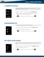
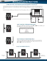
Display Temperature Calibration
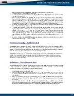
Thermostats are calibrated at the factory and should require no further adjustment. However, the display space
temperature may be field calibrated by the following procedure:
To access the Thermostat Configuration Menu: Tap
While in Thermostat Configuration Menu, Select
Calibrate Display
Use the and arrows to calibrate the thermostat display to a external temperature probe temperature reading.
Tap to save changes, to return to the home screen tap
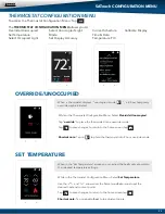
Adjusting Set Points
The Heat or Cool set points are displayed at the bottom of the screen. To adjust the set points, tap on the heat-to
or cool-to temperatures; the set points will be displayed on the screen.
Use the and arrows over the flame/snowflake icons to set the desired heat and cool set points.
Tap to save changes
The Heat and Cool set points can be individually set for the Occupied and Unoccupied modes.
Occupied Mode:
Heat to and Cool to settings - When the Day/Night switch is in the DAY position, or time
clock in Occupied.
Unoccupied Mode:
Heat to and Cool to settings - When the Day/Night switch is in the NIGHT position,
or time clock in Unoccupied.
Changing Mode
The thermostats are auto changeover, but specific modes may be selected. Heat/Cool mode is the default.
System Heat/Cool
- Tap on , select “Heat/Cool”. Tap to save changes
System Heat Only
- Tap on , select “Heat Only”. Tap to save changes
System Cool Only
- Tap on , select “Cool Only”. Tap to save changes
System Off
- Tap on , select “Off”. Tap to save changes
Override Operation
When the thermostat displays the unoccupied icon a 2-hour temporary override may be initiated by tapping
the “Override” will appear. When additional override time is required, tap the unoccupied icon again.
Auxiliary Heat / Reheat
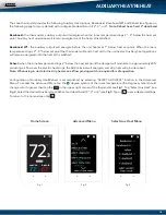
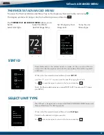
The zone thermostat provides the following Auxiliary Heat options; Baseboard, Baseboard W1 and Reheat (see
figure on the following page for more details) with configurable dead band of 2°, 3°, or 4°.
Note: Reheat has a
fixed 2° dead band. And when using in duct electric strip heater, an airflow proving switch is required for
safe operation.
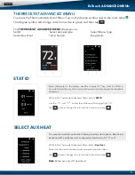
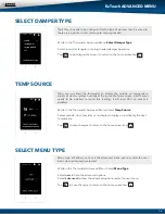
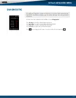
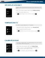
Configuration of Auxiliary Heat/Reheat is accomplished by selecting “SELECT AUX HEAT” function in the
Advanced Menu. To access the Advanced Menu tap the degree symbol of the room temperature (the degree
symbol should change color to green) then tap the in the upper right corner of the thermostat, Tap “Select
Aux Heat”, Select the desired Auxiliary Heat/Reheat and dead band (2°, 3°, or 4°). Tap on to save desired
settings. To return to the home screen tap
BASEBOARD ELECTRIC HEAT
BASEBOARD HYDRONIC HEAT
DUCT FAN REHEAT
VAV DUCT REHEAT
CONTROL
RELAY
HEATING COIL
AIRFLOW
HEAT
RELAY
PROVING SWITCH
CONTROL
DAMPER
H
E
A
T
I
N
G
C
O
I
L
AIRFLOW PROVING SWITCH
RELAY
24 VOLT
FAN
TRANSFORMER
RELAY
HEAT
CONTROL
RELAY
H
E
A
T
I
N
G
C
O
I
L
FAN
24 VOLT
TRANSFORMER
CONTROL
RELAY
HYDRONIC
VALVE
HEATING COIL
AUX
DS
COM
DS
TR1
TR2
MC
RO
RC
GND
A
B
AUX
DS
COM
DS
TR1
TR2
MC
RO
RC
GND
A
B
AUX
DS
COM
DS
TR1
TR2
MC
RO
RC
GND
A
B
AUX
DS
COM
DS
TR1
TR2
MC
RO
RC
GND
A
B
Wire one AUX terminal to the air proving switch from the air proving switch complete wiring to
the terminal on the 24v coil relay. Wire the C terminal to the 24v coil on the relay. Isolate control
power to power baseboard heater.
Wire from AUX/C terminals to the 24v coil on a field supplied SPDT relay. Wire baseboard heat
to the load side of the relay to the baseboard heater.
Wire from the AUX/C to the 24v coil on a field supplied SPDT relay. Wire from one contact
terminal to the 24v coil of the fan relay and to the air proving switch then wire the leaving side
of the air proving switch to the 24v coil relay on the electric stripheater. Now wire the other
contact to the transformer. Wire the other transformer leg to the fan and electric strip heater
24v coil terminals to complete the circuit. Isolated control power should be provided to power
the fan and electric strip heater.
Wire from AUX/C to 24v coil on a SPDT relay then wire from one contact terminal to the
transformer and from the other transformer leg to the valve. On the other relay contact
terminal wire to the valve to complete the circuit. Isolated control power should be provided
to power the valve.


