22
INSTALLATION INSTRUCTIONS
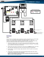
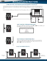
Wiring to Communication Terminals
Red-A
White-B
Black-GND
Using Zonex TWPR communication wire. Wire
IN
and
OUT
of A, B, GND to and
from SATouch's in a daisy chain configuration.
SATouch is powered by the independent transformer connected to the
GEN II. Using 18/2 wire for the 24vac power, daisy chain from TR1, TR2
IN
and
OUT
to and from the SATouch's.
Daisy Chain Multiple SATouch's
WIRING THE UNIT, SUPPLY AND RETURN AIR SENSORS TO THE SATouch
DAISY CHAIN THE COMMUNICATION WIRE
DAISY CHAIN 24V POWER FROM GEN II
Use 18/6 thermostat wire, wire from SATouch to the RTU/split system. Make sure to match up the unit terminals to
the SATouch terminals R, Y1, Y2, W1/O/B, W2, G. Wire in the Supply and Return air sensors using 18/4 thermostat
wire.
Install the Supply and Return air LAT sensors 18 to 24” downsteam of the unit.
Y2
W2
GND
A
B
W1-O/B
G
Y1
R
TR1
TR2
Y2
W2
GND
A
B
OCP
OCP
W1-O/B
G
Y1
R
TR1
TR2
OCP
Y2
W2
GND
A
B
W1-O/B
G
Y1
R
TR1
TR2
OCP
Y2
W2
GND
A
B
OCP
Y2
W2
GND
A
B
OCP
Y2
W2
GND
A
B
OCP
OCP
OCP
W1-O/B
G
Y1
R
TR1
TR2
W1-O/B
G
Y1
R
TR1
TR2
W1-O/B
G
Y1
R
TR1
TR2
Daisy Chain from
GEN II
Daisy Chain to
additional SATouch’s
OCP
HVAC UNIT
SUPPLY
RETURN


