


AEMZP0BA - EPS-AC0 - User Manual
Page - 89/95
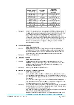
WHEEL ANGLE
[degrees]
Admitted
sector
Admitted
FEEDBACK
SECTOR
-22 to +22
1
st
or 4
th
3.13 V or 1.88 V
+23 to +67
1
st
3.13 V
+68 to +112
1
st
or 2
nd
3.13 V or 4.39 V
+113 to +157
2
nd
4.39
V
+158 to -158
2
nd
or 3
rd
4.39 V or 0.62 V
-157 to -113
3
rd
0.62
V
-112 to -68
3
rd
or 4
th
0.62 V or 1.88 V
-67 to -23
4
th
1.88
V
- Remedy:
Check the potentiometer connected to CNB#6 is right working. If
toggle switches are connected to CNA#2 and CNA#3, verify they
are right working and the setting AUX FUNCTION 11 (see
12.4.1.9) is correct. Verify also the sensor bearing in the motor
(encoder) has not a slip (the sensor bearing has two rings: one is
connected to the rotor shaft; the other is connected to the motor
frame. Check these two rings are strictly connected to their
structure without slip.
6) STEER SENSOR KO
CAN Bus Code =84
- Cause:
This alarm occurs if the command potentiometer (CPOC1 on
CNA#9 or CPOC2 on CNA#8) changes with a jerk larger than
MAX SP SLOPE (see 12.4.6.3). This alarm is used to catch a
discontinuity in the voltages of the command potentiometer.
- Remedy:
Change the twin pot.
7) JERKING FB POT
CAN Bus Code =223
- Cause:
This alarm occurs if the feedback potentiometer (CPOT on
CNB#6) changes with a jerk larger than 0.3 V in 16 msec. This
alarm is used to catch a discontinuity in the voltages of the
feedback potentiometer.
- Remedy:
Change the feedback potentiometer.
8) FB POT LOCKED or FB SENS LOCKED
CAN Bus Code =222
- Cause:
In application with a feedback potentiometer, this alarm occurs if
the feedback potentiometer (CPOT on CNB#6) does not change
(or changes in the opposite direction) its value even if commanded
to change.
In application with toggle switches with ENCODER CONTROL to
off, this alarm occurs if the feedback encoder counting does not
change its value even if commanded to change.
- Remedy:
In application with the feedback potentiometer, verify the feedback
potentiometer is not mechanically loosened. Check there is not a
mechanical block of the steered wheel.
Be sure the wiper has not reached its own electrical limit because
of too much angle of the steered wheel.
Besides, this alarm may occur at the installation when the motor
rotates in the wrong direction turning away from the wished
Содержание EPS-AC0
Страница 23: ...AEMZP0BA EPS AC0 User Manual Page 23 95 6 2 EPS AC0 Stepper Motor diagram Figure 6 2...
Страница 24: ...Page 24 95 AEMZP0BA EPS AC0 User Manual 6 3 EPS AC0 Twin pot diagram Figure 6 3...
Страница 54: ...Page 54 95 AEMZP0BA EPS AC0 User Manual 12 3 1 Stepper motor with Encoder and Feedback pot Figure 12 2...
Страница 55: ...AEMZP0BA EPS AC0 User Manual Page 55 95 12 3 2 RTC with Encoder and Feedback pot Figure 12 3...
Страница 56: ...Page 56 95 AEMZP0BA EPS AC0 User Manual 12 3 3 Stepper motor with Encoder and Toggle switch es Figure 12 4...