


AEMZP0BA - EPS-AC0 - User Manual
Page - 59/95
1) HOUR
COUNTER
This option specifies the hour counter mode. It can be set one of two:
-
RUNNING:
The counter registers travel time only.
-
KEY ON:
The counter registers when the "key" switch is closed.
2) MICRO
CHECK
This option is useful to support debug and troubleshooting. It makes possible to
inhibit the supervisor (Slave uC) operations and allows the system to run with
just the Main uC.
When entering this operating mode the safety contacts stay
open. Therefore, traction shall be disabled. It can be set one of two:
-
PRESENT:
Default setting: enable the operations of the supervisor
(Slave uC).
-
ABSENT:
Disable the operations of the supervisor (Slave uC). The
safety contacts stay opened.
3) FEEDBACK
DEVICE
This option specifies which kind of Feedback Sensor is adopted. Here is the
feedback sensor list:
-
OPTION #1: FB POT only.
The only feedback sensor is the potentiometer at the steered
wheel. This setting must be temporary chosen for the set-up
of the FB ENC & FB POT configuration (see below). After
the set-up is ended, it is necessary to turn FEEDBACK
DEVICE to OPTION #2 to get the steer working with FB ENC
& FB POT.
-
OPTION #2: FB POT & FB ENC.
This is the right setting when the encoder is chosen together
with the FB POT. Pay attention, the set-up must be done
with the FEEDBACK DEVICE to OPTION #1. When the set-
up is finished, turn to OPTION #2. When the FEEDBACK
DEVICE is OPTION #2 an automatic centering is always
carried out at key-on.
-
OPTION #3: FB POT & FB ENC & ONE TOGGLE SWITCH
This is the right setting when the encoder is chosen together
with the FB POT and a straight ahead toggle switch (SW1).
Pay attention, the set-up must be done with the FEEDBACK
DEVICE to OPTION #1. When the set-up is finished, turn to
OPTION #3. When the FEEDBACK DEVICE is OPTION #3
an automatic centering is always carried out at key-on.
-
OPTION #4: FB ENC & ONE (or TWO) TOGGLE SWITCHES
This is the right setting when the FB POT is not present and
two toggle switches are adopted (normally in the straight and
90 degrees angled positions of the steered wheel). At key
on, an Automatic Centering operation is executed seeking
the Toggle Switch signal (SW1 on CNA#3). When the Toggle
Switch edge is met the Encoder counter is zeroed. The 2
nd
Switch (SW2 on CNA#2) is used to verify the encoder
counter at 90° is matched with the SW2 transition.
4) LIMIT
DEVICE
(Versions with FEEDBACK DEVICE to OPTION #1, 2, 3 only). When this option
is set ON, the steered wheel angle will be limited using the feedback sensor
value. It can be set one of two:
-
ON:
When the feedback sensor overtakes either the CW or the
CCW limit (see 12.4.2.13-14, SET MAX FB POT, SET MIN
Содержание EPS-AC0
Страница 23: ...AEMZP0BA EPS AC0 User Manual Page 23 95 6 2 EPS AC0 Stepper Motor diagram Figure 6 2...
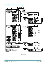
Страница 24: ...Page 24 95 AEMZP0BA EPS AC0 User Manual 6 3 EPS AC0 Twin pot diagram Figure 6 3...
Страница 54: ...Page 54 95 AEMZP0BA EPS AC0 User Manual 12 3 1 Stepper motor with Encoder and Feedback pot Figure 12 2...
Страница 55: ...AEMZP0BA EPS AC0 User Manual Page 55 95 12 3 2 RTC with Encoder and Feedback pot Figure 12 3...
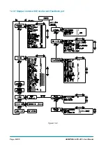
Страница 56: ...Page 56 95 AEMZP0BA EPS AC0 User Manual 12 3 3 Stepper motor with Encoder and Toggle switch es Figure 12 4...