


AEMZP0BA - EPS-AC0 - User Manual
Page - 67/95
functions. With this choice, the automatic functions are
inhibited (the AUTC function isn’t possible).
- LEVEL
5:
Single pot with feedback sensor.
This is a closed loop
configuration. The single pot supplies the commanded
position for the steered wheel. The feedback sensor is
mandatory to close the loop with the commanded position.
This choice is just for testing a prototype before to gather a
twin pot; we strongly advice against using this configuration
for the field production.
The FEEDBACK DEVICE option (see 12.4.1.3) specifies
which kind of feedback sensor is adopted.
- LEVEL
6:
Via CAN demanded speed without feedback sensor.
This
is an open loop configuration. A remote unit provides the
wished steering motor speed via CAN Bus. As the feedback
sensor is not strictly necessary in open loop mode, it is
possible to work without feedback sensor at all. In spite of
that, when the maximum angle limitation via feedback
sensors is enabled (option LIMIT DEVICE to ON when
FEEDBACK DEVICE is OPTION #1-2-3; 1
ST
ANGLE
COARSE and 2
ND
ANGLE COARSE less than level 9 when
FEEDBACK DEVICE is OPTION #4), the feedback sensor is
expected to perform the secondary functions of maximum
angle limitation, detection of the locked motor and to perform
the alignment at the rest position. When these conditions are
met, the FEEDBACK DEVICE option (see 12.4.1.3) specifies
which kind of feedback sensor is adopted for the secondary
functions. With this choice, the automatic functions are
inhibited (the AUTC function isn’t possible).
In the above list, the configurations with the command via CAN Bus may be
developed only if the communication protocol between eps-ac0 and remote unit
is known.
2) AUTO
REQ
TYPE
Level 0 to 9.
This setting specifies the type of the automatic request. The
standard version foresees no automatic function so this setting is ineffective.
The only exception is the configuration FEEDBACK DEVICE to OPTION #4
(encoder and toggle switches). Then the automatic centering is regulated with
the option AUTOCENTERING (see 12.4.1.5). AUT REQ TYPE will be handled
time to time according the automatic function customer’s specification.
3) CONNECTED
TO
It assumes a number between 0 to 255.
This setting is used to (virtually)
connect the hand-set
to a remote unit CAN Bus connected. With the hand-set
connected to the eps-ac0 it is possible to communicate with a remote Zapi unit.
Every Zapi unit has its own identification number (e.g. eps-ac0 is 6; traction
controller is 2; pump controller is 1).
By setting CONNECTED TO to 2, the hand set will be virtually connected to the
traction controller.
4) MODEL
TYPE
It assumes a number between 0 to 3.
This setting is used to specify which one
local elaboration unit must be virtually connected to the hand-set.
In fact eps-ac0 has two uCs aboard. When MODEL TYPE is set to 0, the hand
set is communicating with the main uC; when MODEL TYPE is set to 1, the
hand set is communicating with the slave uC.
Содержание EPS-AC0
Страница 23: ...AEMZP0BA EPS AC0 User Manual Page 23 95 6 2 EPS AC0 Stepper Motor diagram Figure 6 2...
Страница 24: ...Page 24 95 AEMZP0BA EPS AC0 User Manual 6 3 EPS AC0 Twin pot diagram Figure 6 3...
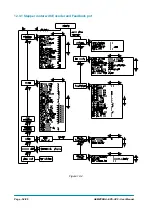
Страница 54: ...Page 54 95 AEMZP0BA EPS AC0 User Manual 12 3 1 Stepper motor with Encoder and Feedback pot Figure 12 2...
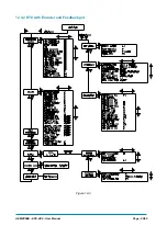
Страница 55: ...AEMZP0BA EPS AC0 User Manual Page 55 95 12 3 2 RTC with Encoder and Feedback pot Figure 12 3...
Страница 56: ...Page 56 95 AEMZP0BA EPS AC0 User Manual 12 3 3 Stepper motor with Encoder and Toggle switch es Figure 12 4...