Zapi EPS-AC0 Скачать руководство пользователя страница 82

Page - 82/95 

AEMZP0BA - EPS-AC0 - User Manual 

13 OTHER  FUNCTIONS 

Here is a list of special functions hand set assisted, that are not documented yet.   

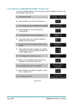
13.1  Acquiring the Motor resistance 

When it is possible, the steering motor is controlled sensorless. To get the best 
performance in terms of the max torque generated, it is necessary to compensate 
for the drop in the motor resistance. So the correct value of the motor resistance 
must be known.  
Eps-ac0 provides a self-acquisition procedure to acquire the motor resistance.  
It is just enough to connect the eps-ac0 to the battery, to the motor and to the wiring 
in order no alarm occurs. Then: 
1)  Enter the ADJUSTMENTS menu searching for ADJUSTMENT #01 setting. 
2)  Turn ADJUSTMENT #01 to Level 1. (A DATA ACQUISITION alarm occurs and 

a half Imax DC current is automatically injected in the motor).  

3)  Wait about 2 secs. 
4)  Roll ADJUSTMENT #01 back to Level 0. 
5)  Save the new setting. 
With this procedure the resistance between two motor terminals is automatically 
measured and recorded (in milliohms) on the ADJUSTMENT #02 (see 12.4.2.3). 
It is also possible to adjust the motor resistance value without self-acquisition by 
rolling the ADJUSTMENT #02. 
The acquisition of the motor resistance should be performed to find the correct value 
when developing a new truck prototype; the correct value will be the default setting 
for the mass production of that truck.        

13.2  Alignment at the rest position 

In the open loop applications (i.e. when the stepper motor is used in the steering 
wheel or the steer command is a speed information coming via CAN bus) an 
alignment at the rest position is automatically performed when the steered wheel 
has a drift with a released steering wheel. This alignment at the rest position is 
handled closed loop and so a feedback sensor is required. So this function is 
performed only either with SYSTEM CONFIG to level 0 or with SYSTEM CONFIG to 
level 4. When the feedback sensor uses a feedback potentiometer, the alignment at 
rest position is performed for both cases (SYSTEM CONFIG to level 0 and 4) 
provided that option LIMIT DEVICE is ON. When the feedback sensor uses toggle 
switches, the alignment at the rest position is performed only when SYSTEM 
CONFIG is level 0. 

13.3  Straight ahead steering numbness 

It is possible to reduce the steering sensitivity while the steered wheel is close to be 
straight ahead by using the NUMBNESS setting in the PARAMETERS CHANGE 
menu. Increasing the NUMBNESS parameter gets the steering less responsive 
when the truck is driving next to the straight ahead direction (i.e. a certain increment 
of the steering wheel angle gets a smaller increment of the steered wheel angle 
when the truck is driving straight ahead than when it is angled).  

Содержание EPS-AC0

Страница 1: ...LECTRONIC OLEODYNAMIC INDUSTRIAL EQUIPMENTS CONSTRUCTION Via Parma 59 42028 POVIGLIO RE ITALY Tel 39 0522 960050 r a Fax 39 0522 960259 e mail zapi zapispa it web www zapispa it EN User Manual EPS AC0...

Страница 2: ...anges or improvements to its products at any time and without notice The present publication reflects the characteristics of the product described at the moment of distribution The publication therefo...

Страница 3: ...edback Potentiometer 15 4 5 2 Encoder in the motor shaft and one two toggle switch es 17 4 5 3 Feedback Encoder 18 5 AUTC MODE 21 6 CONNECTING DIAGRAMS 22 6 1 Power Connecting Diagram 22 6 2 EPS AC0 S...

Страница 4: ...49 11 1 4 RTC AUTC 50 11 2 Quick set up 50 11 2 1 Stepper Motor only 50 11 2 2 Stepper Motor AUTC 51 11 2 3 RTC only or RTC AUTC 51 12 PROGRAMMAING ADJUSTMENTS USING DIGITAL CONSOLE 52 12 1 Adjustment...

Страница 5: ...ix Blinks Alarms 91 14 1 7 Thirty two Blinks Alarms 92 14 1 8 No Blink Alarms Warning 92 14 2 CAN BUS ALARMS List 93 15 RECOMMENDED SPARE PARTS 94 16 PERIODIC MAINTENANCE TO BE REPEATED AT TIMES INDIC...

Страница 6: ...ry low resolution encoder 4 pulses rev are more than enough mounted on the steering motor shaft The on board CAN interface makes the communication exchange between our eps ac0 and other units in the t...

Страница 7: ...e 1024 steps resolution Analog KTY84 130 thermal sensor input Analog input with 1024 steps resolution one input Analog input with 4096 steps resolution one input Two digital inputs Double Safety Relay...

Страница 8: ...ZP0BA EPS AC0 User Manual Minimum Input key Supply Voltage after start up 12 V 2 4 Mechanical specifications 2 4 1 Basic release It has Molex Minifit connector with international protection IP54 EPS A...

Страница 9: ...to limit the angle With a Multiturn steering wheel the sensor in the hand wheel shall be a stepper motor used as a tacho generator see Figure 3 1 Then the control will turn the steering motor moving a...

Страница 10: ...otor or the twin pot without hardware modification It is just enough to set the SYSTEM CONFIG to the correct value see 12 4 3 1 3 2 Automatic Centering Automatic Centering turns the steered wheel stra...

Страница 11: ...Special Debugging Troubleshooting system makes easier the fault catching 10 Possibility to run in a stand alone not CAN Bus supported configuration 11 Motor control may be performed with or without e...

Страница 12: ...io close to 1 50 2 External gears ratio close to 1 4 The maximum continuous output torque requirement changes with the truck type As a thumb rule and in the worst case stalled steer 1 A low level OP a...

Страница 13: ...AEMZP0BA EPS AC0 User Manual Page 13 95 4 3 1 Eps ac0 PCB It has Molex Minifit connector with international protection IP54 Figure 4 1...

Страница 14: ...e following part numbers resulted suited to work with eps ac0 1 MINEBEA Type code AA23KM K227 T20V 2 JAPAN SERVO Type Code KH56JM2X 1269 DC12V 30 ohm They have the same mechanical dimensions see Figur...

Страница 15: ...ack sensors Feedback sensors are mandatory to close the loop in manual mode if a twin pot is mounted on the steering wheel Feedback sensors are strongly suggested to improve safety in manual mode if a...

Страница 16: ...eter The feedback potentiometer is used for both encoder initialisation and redundancy on the steered wheel angle measurement Normally the feedback potentiometer is multiturn 5 or 10 turns 5K hybrid t...

Страница 17: ...ut CNA 2 and GND 3 Feedback encoder on the steering motor shaft Figure 4 5 4 5 2 1 Straight ahead toggle switch The straight ahead toggle switch must be of NPN type i e it must connect a minus battery...

Страница 18: ...n the steered wheel is in the 90 degrees limiting position This second toggle switch must be connected to CNA 2 and GND minus battery Iro n Plate Steered wh eel Pro x switch 90 Pro x switch Figure 4 7...

Страница 19: ...fied in the headline of the handset showing something like EPSAC0S2A ZP0 70 That means EPSAC0 Eps ac0 steering controller S Stepper motor 2 poles pair number A 32 pulses rev encoder ZP SW release type...

Страница 20: ...s rev S 6 pulses rev W 16 pulses rev A 32 pulses rev K 48 pulses rev B 64 pulses rev The letters to specify the poles pair number and the Encoder resolution are present only if the SW includes the fun...

Страница 21: ...rnative it is possible to use wired requests For example 1 in a configuration with feedback pot and feedback encoder it is possible to use inputs CNA 3 and CNA 2 for the centering request redundancy i...

Страница 22: ...ING DIAGRAMS Below we have a collection of suggested connecting diagrams They correspond to the main configurations On request it is possible to choose also customized proposals or wiring modification...

Страница 23: ...AEMZP0BA EPS AC0 User Manual Page 23 95 6 2 EPS AC0 Stepper Motor diagram Figure 6 2...

Страница 24: ...Page 24 95 AEMZP0BA EPS AC0 User Manual 6 3 EPS AC0 Twin pot diagram Figure 6 3...

Страница 25: ...mon wire is broken 7 2 Twin pot connections The twin pot is connected in alternative to the stepper motor between CNB 5 PPOC 5 V positive supply CNA 10 negative supply CNA 9 CPOC1 1st wiper CNA 8 CPOC...

Страница 26: ...CNA 2 have the function to limit the maximum steered angle in CW and CCW side in alternative it is possible to use them as centering request CNA 3 and CNA 2 are detected low if they are lower than 1...

Страница 27: ...5 and CNA 4 The Main microprocessor manages the first contact the Supervisor microprocessor manages the second contact U Note If the safety switch is connected in series with external switches dead ma...

Страница 28: ...on the current drawn and the duty cycle 8 1 1 Controller with Base Plate Installs the controller with the base plate on a flat metallic surface that is clean and unpainted suggested characteristics a...

Страница 29: ...upply the controller only with battery for traction do not use a power supply U When the inverter is installed simulate a steering alarm and verify that both traction and electromechanical brake shall...

Страница 30: ...ac0 is not strictly required In fact in an AC system the steer is automatically de energized when a power failure occurs In a DC system with permanent magnet motor instead a short circuit in a power...

Страница 31: ...ent a simple double wire cable or a duplex cable not shielded In a system like an industrial truck where power cables carry hundreds of Ampere there are voltage drops due to the impedance of the cable...

Страница 32: ...yout but can bring to errors in the can line The best solution depends on the type of nodes modules connected in the network If the modules are very different in terms of power then the preferable con...

Страница 33: ...and voltage drop problems 4 Can advantages The complexity of today systems needs more and more data signal and information must flow from a node to another CAN is the solution to different problems th...

Страница 34: ...ng motor Basically the two microcontrollers implement a double check control of the main functions The two Cs are both CAN Bus connected This characteristic makes possible the eps ac0 receives the ste...

Страница 35: ...ize the antenna effect cables running nearby the truck frame or in iron channels connected to truck frame is generally a suggested not expensive solution to reduce the emission level 8 9 2 Electromagn...

Страница 36: ...is necessary to avoid that the devices connected to the CAN communication system have exposed metallic head terminals The operator shall not get in touch with any metallic part of the devices CAN Bus...

Страница 37: ...Use the FB ENC instead of the FB POT as feedback sensor The Encoder has not noise When the Encoder is stopped in a position the Encoder counting is absolutely constant 3 Reduce the gain of the Closed...

Страница 38: ...Page 38 95 AEMZP0BA EPS AC0 User Manual 9 DESCRIPTION OF THE CONNECTORS W V B U B CNC 1 8 8 5 4 1 8 1 7 14 CNB CNA EPS AC0 Figure 9 1...

Страница 39: ...her Voltage Point A6 CANL Can Bus Low A7 KEY Key in 24 36 Vbatt A8 CPOC2 QL 2nd SP POT Wiper or Stepper Motor Q line A9 CPOC1 DL 1st SP POT Wiper or Stepper Motor D line A10 NPOC Twin SP POT Negative...

Страница 40: ...erial reception C2 NCLRXD Negative serial reception C3 PCLTXD Positive serial transmission C4 NCLTXD Negative serial transmission C5 GND Negative console power supply C6 12 Positive console power supp...

Страница 41: ...f power connections View of the power bars W V B U B CNC 1 8 8 5 4 1 8 1 7 14 CNB CNA EPS AC0 Figure 9 3 B Negative of the battery B Positive of the battery U V W Connection bars of the three motor ph...

Страница 42: ...describes the step by step installation procedure to get the prototype working in manual mode to raise the AUTC function it is necessary to make the complete set up procedure see topic 11 For every tr...

Страница 43: ...or the maximum plus 90 degrees limit position If present the maximum of the FB ENC is recorded too although it is not shown in the hand set Step14 Move the steering wheel until the minimum minus 90 de...

Страница 44: ...ading ENC SPEED in the tester menu is consistent with the reading FREQUENCY in the tester menu Consistent means that ENC SPEED and FREQUENCY must have the same sign and a close value If ENC SPEED has...

Страница 45: ...in the adjustments menu Save and recycle the key After the acquisition the SET FBPOT AT SW1 value should be close to the 2 5 V value otherwise it is necessary to re make the FB POT mounting in such a...

Страница 46: ...he FEEDBACK POT reading in the TESTER menu Step12 With the steered wheel in the maximum angle plus 90 degrees enter and save the adjustment SET MAX FB POT on the hand set to memorize the steer angle f...

Страница 47: ...encoder counting corresponding to a steered wheel revolution To do that turn the steered wheel some revolutions in CW direction and read the ENC COUNT AT 360 in the tester menu At every falling edge o...

Страница 48: ...d position null WHEEL ANGLE or to the 180 degrees position depending by this setting Step18 Parameters 1ST ANGLE COARSE and 2ND ANGLE COARSE set the maximum steered wheel angle respectively in the pos...

Страница 49: ...y Connect a traction travel demand to CNA 1 It can be a tiller switch or a dead man or a seat switch This operation supplies the information the truck is moving or not to stand by the steer when the t...

Страница 50: ...or damping during the pursuing operation see paragraph 12 4 4 Step11 CAN Bused system only Set the Dynamic Numbness in closed loop steering sensitivity reduces when the truck speed increases The param...

Страница 51: ...straight travelling when automatic centered 11 2 3 RTC only or RTC AUTC In a truck working closed loop in manual mode with a Twin Pot connected on the Return To Center handlebar with or without the A...

Страница 52: ...G DIGITAL CONSOLE 12 1 Adjustments via console Adjustment of Parameters and changes to the inverter s configuration are made using the Digital Console The Console is connected to the CNC connector of...

Страница 53: ...AC inverter controllers must be fitted with EPROM CK ULTRA minimum Release Number 3 02 The section describes the Zapi hand set functions Numbers inside the triangles correspond to the same number on t...

Страница 54: ...Page 54 95 AEMZP0BA EPS AC0 User Manual 12 3 1 Stepper motor with Encoder and Feedback pot Figure 12 2...

Страница 55: ...AEMZP0BA EPS AC0 User Manual Page 55 95 12 3 2 RTC with Encoder and Feedback pot Figure 12 3...

Страница 56: ...Page 56 95 AEMZP0BA EPS AC0 User Manual 12 3 3 Stepper motor with Encoder and Toggle switch es Figure 12 4...

Страница 57: ...iguration with stepper motor against the one with RTC in the hand wheel besides we distinguish between the configuration with the encoder plus toggle switches against the one with the encoder plus pot...

Страница 58: ...ow SET MODEL CONFIG MENU SET MODEL Press ROLL UP or ROLL DOWN button until SET OPTIONS menu appear The Display will show SET OPTIONS CONFIG MENU SET OPTIONS Press ENTER to go in the SET OPTIONS MENU T...

Страница 59: ...hosen together with the FB POT Pay attention the set up must be done with the FEEDBACK DEVICE to OPTION 1 When the set up is finished turn to OPTION 2 When the FEEDBACK DEVICE is OPTION 2 an automatic...

Страница 60: ...he steering control is alternatively turned off 15 secs long plus the AUXILIARY TIME and on 3 secs long LEVEL 2 The steering control is alternatively turned off 15 secs long plus the AUXILIARY TIME an...

Страница 61: ...tion depending by this setting 12 POT UP SW1 EDGE only when FEEDBACK DEVICE is OPTION 3 It is possible to reverse the turning direction of the steered wheel during the initial alignment To do that an...

Страница 62: ...ter CONFIG MENU 3 The Display will show SET MODEL CONFIG MENU SET MODEL 4 Press ROLL UP button until ADJUSTMENTS MENU appears 5 ADJUSTMENTS appears on the display CONFIG MENU ADJUSTMENTS 6 Press ENTER...

Страница 63: ...s the motor weakened 8 OVERSAT FREQ The maximum motor frequency is set with the sum between SET SAT FREQ and OVERSAT FREQ OVERSAT FREQ is the increment over the SET SAT FREQUENCY in which the steering...

Страница 64: ...rresponding to a complete steered wheel revolution It is used in the arrangements using the FB ENC and Toggle switches to properly scale the encoder counting with the steered wheel angle WHEEL ANGLE 1...

Страница 65: ...SAC0 S ZP0 70 24V 50A 00000 2 Press Top Left Right Buttons to enter CONFIG MENU 3 The Display will show SET MODEL CONFIG MENU SET MODEL 4 Press ENTER to go into the SET MODEL MENU 5 The display will s...

Страница 66: ...strictly necessary in open loop configuration in spite of that this setting specifies the feedback sensor is present and it will be used for the automatic function AUTC maximum angle limitation detec...

Страница 67: ...ifies which kind of feedback sensor is adopted for the secondary functions With this choice the automatic functions are inhibited the AUTC function isn t possible In the above list the configurations...

Страница 68: ...show the first parameter SPEED LIMIT LEVEL 7 6 Press either ROLL UP and ROLL DOWN to display the next parameter 7 The names of the Parameters appear on the Display SENSITIVITY LEVEL 0 8 When desired...

Страница 69: ...speed To get this goal this setting adjusts the maximum angle at full truck speed When the truck speed increases the maximum steered wheel angle reduces proportionally When the truck is full speed the...

Страница 70: ...g wheel is slow turning This attenuation must be proportional to the drive speed At full drive speed the attenuation of the scaling factor is maximum AUX FUNCTION 2 to Level 0 means no attenuation of...

Страница 71: ...respondence between the steering motor speed and the angle error between the actual commanded position and the latest steady state position of the steered wheel This parameter sets the percentage of t...

Страница 72: ...FEEDBACK ENC reading By increasing this parameter the maximum steered wheel angle increases too The maximum angle in RTC should be regulated in feedforward way by properly adjusting the angle setting...

Страница 73: ...t ahead direction Intermediate reductions of sensitivity are applied for intermediate settings The steering sensitivity increases in a proportional relationship with the increased steering wheel angle...

Страница 74: ...ing and dither close to the commanded position Obviously lag and lead regulations influence the stability of the closed loop and so different setting must be empirically tried to avoid oscillations LE...

Страница 75: ...2 CAN BUS ABSENT or PRESENT This setting specifies whether the eps ac0 is CAN Bus connected or not When CAN BUS is ABSENT the CAN BUS KO alarm is inhibited together with any starting sequence used to...

Страница 76: ...n 16 msec LEVEL 3 the max admitted slope is 115 corresponding to 0 56 V in 16 msec LEVEL 4 the max admitted slope is 133 corresponding to 0 65 V in 16 msec LEVEL 5 the max admitted slope is 151 corres...

Страница 77: ...hand setting LEVEL 12 The SET POINT POT of the Tester menu is connected at the high resolution AD input it is in the range 0 to 5Vdc when the command potentiometer CPOC1 is close to ZERO SP POT LEVEL...

Страница 78: ...ctor quadrant detected through the toggle switches It assume the following value 3 13 V in the sector from 0 to 90 degrees 4 39 V in the sector from 90 to 180 degrees 0 62 V in the sector from 180 to...

Страница 79: ...el angle will be limited and CW LIMIT LEVEL turns ON active 16 ACW LIMIT LEVEL When the maximum angle limitation via feedback sensors is enabled option LIMIT DEVICE to ON when FEEDBACK DEVICE is OPTIO...

Страница 80: ...meters In particular When the special adjustments DEBUG OUTPUT is other than Level 12 or 13 SLOPE PEAK supplies the slope peak of the CPOC1 set point potentiometer CNA 9 When the special adjustments D...

Страница 81: ...BACK DEVICE is OPTION 4 This reading shows the encoder counting between two falling edges on the straight ahead switch It must be meant as the encoder counting corresponding to a steered wheel revolut...

Страница 82: ...hen developing a new truck prototype the correct value will be the default setting for the mass production of that truck 13 2 Alignment at the rest position In the open loop applications i e when the...

Страница 83: ...a mechanical fault or to a failed sensor or to a problem in the motor It is difficult to find the root for the problem in the short time before the alarm occurs For this reason the eps ac0 provides a...

Страница 84: ...r motor application this alarm occurs if the main uC is detecting a direction of the stepper motor not matched with the one that the slave uC is detecting In closed loop application this alarm occurs...

Страница 85: ...e main uC through this serial interface Remedy It is necessary to replace the controller 7 SLAVE COM ERROR CAN Bus Code 227 Cause Main uC and Slave uC communicate via a local serial interface This ala...

Страница 86: ...indow from 2 2 to 2 8 and not in the range to generate the reset on demand the slave uC raises this alarm Remedy It is necessary to replace the controller 14 1 2 Two Blinks Alarms 1 HIGH CURRENT CAN B...

Страница 87: ...If this information lacks more than about 1 5 secs this alarm occurs Remedy Find on the traction controller the reason for keeping the main contactor open 8 CAN BUS KO CAN Bus Code 247 Cause This ala...

Страница 88: ...one connection of the command potentiometer is broken 4 F B OUT OF RANGE CAN Bus Code 249 Cause This alarm occurs for a fault on the feedback potentiometer CPOT on CNB 6 This alarm occurs if CPOT exit...

Страница 89: ...h a discontinuity in the voltages of the command potentiometer Remedy Change the twin pot 7 JERKING FB POT CAN Bus Code 223 Cause This alarm occurs if the feedback potentiometer CPOT on CNB 6 changes...

Страница 90: ...wrong connection between the two encoder channels In this latest case exchange in between the two encoder channels 11 BAD ENCODER SIGN CAN Bus Code 83 Cause It occurs in applications with toggle switc...

Страница 91: ...mperature in the motor higher than 150 degree still with DIAG MOTOR TEMP to ON Remedy Check the thermal sensor in the motor is right working If it is improve the cooling of the motor 14 1 6 Six Blinks...

Страница 92: ...peed reduction occurs on the traction 2 WAITING DATA CAN Bus Code 237 Cause This warning occurs only if CAN BUS is PRESENT At key on the eps ac0 asks to the traction controller to send a list of param...

Страница 93: ...POWER FAILURE 1 83 BAD ENCODER SIGN 84 STEER SENSOR KO 85 STEER HAZARD 99 INPUT ERROR 1 212 MICRO SLAVE 8 218 CLOCK PAL NOT OK 219 STEPPER MOTOR MISM 220 MOTOR LOCKED 221 MICRO SLAVE 4 222 FB POT LOC...

Страница 94: ...Page 94 95 AEMZP0BA EPS AC0 User Manual 15 RECOMMENDED SPARE PARTS Part number Description C36090 Stepper motor minebea E07161 Twin pot C38207 Best motor 300 W AC motor and P62 DMS gear box 1 51...

Страница 95: ...g a Zapi Agent The supplier is not responsible for any problem that arises from wiring methods that differ from information included in this Manual During periodic checks if a technician finds any sit...

Отзывы: