


Page - 88/95
AEMZP0BA - EPS-AC0 - User Manual
stepper motor at rest) is expected being very low (close to 30
ohms).
2) Q LINE SENSOR KO
CAN Bus Code = 242
- Cause:
This alarm occurs when the mean voltage on the Quadrature line
of the stepper motor (connection CNA#8) is not null: the voltage on
every stepper motor line is a sine wave with null mean voltage.
- Remedy:
Check the continuity of the stepper motor connections. In particular
the resistance between CNA#8 and the minus battery (with the
stepper motor at rest) is expected being very low (close to 30
ohms).
3) S.P OUT OF RANGE
CAN Bus Code =248
- Cause:
This alarm occurs for a fault on the command potentiometer
(CPOC1 on CNA#9, CPOC2 on CNA#8).
When a single command pot is chosen, the alarm occurs if its
wiper (CPOC1) exits the range from 0.8 Vdc to 4.2 Vdc.
When the twin pot is chosen, the alarm occurs if the sum of the
two wiper voltages (CPOC1+CPOC2) exits the range from 4.5 Vdc
to 5.5 Vdc.
- Remedy:
Check the connections of the potentiometer. This alarm occurs
when one connection of the command potentiometer is broken.
4) F.B OUT OF RANGE
CAN Bus Code =249
- Cause:
This alarm occurs for a fault on the feedback potentiometer (CPOT
on CNB#6). This alarm occurs if CPOT exits the range from 0.3
Vdc to 4.7 Vdc.
- Remedy:
Check the connections of the feedback potentiometer. This alarm
occurs when one connection of the feedback potentiometer is
broken.
5) POSITION
ERROR
CAN Bus Code =228
- Cause:
This alarm occurs for an error in the redundant test of the feedback
sensors.
1) When the feedback potentiometer is used together with the
feedback encoder, the angle of the steered wheel is measured
with both of them: FEEDBACK ENC and FEEDBACK POT in the
tester menu are expected to be equal. When they are different
more than 20 degrees this alarm occurs (SET MAX FB POT–SET
MIN FB POT corresponds to 180 degrees).
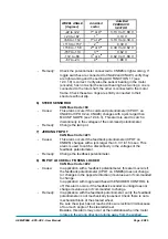
2) When the feedback encoder is used together with toggle
switches, this alarm occurs if the sector (toggles switches
configuration) and the encoder counting are not matched. The
sector is provided via the FEEDBACK SECTOR reading in the
tester menu; the encoder counting is provided via the WHEEL
ANGLE reading in the tester menu. In particular (in case of two
toggle switches):
Содержание EPS-AC0
Страница 23: ...AEMZP0BA EPS AC0 User Manual Page 23 95 6 2 EPS AC0 Stepper Motor diagram Figure 6 2...
Страница 24: ...Page 24 95 AEMZP0BA EPS AC0 User Manual 6 3 EPS AC0 Twin pot diagram Figure 6 3...
Страница 54: ...Page 54 95 AEMZP0BA EPS AC0 User Manual 12 3 1 Stepper motor with Encoder and Feedback pot Figure 12 2...
Страница 55: ...AEMZP0BA EPS AC0 User Manual Page 55 95 12 3 2 RTC with Encoder and Feedback pot Figure 12 3...
Страница 56: ...Page 56 95 AEMZP0BA EPS AC0 User Manual 12 3 3 Stepper motor with Encoder and Toggle switch es Figure 12 4...