


Page - 48/95
AEMZP0BA - EPS-AC0 - User Manual
ENDSTROKE CW=OFF and ENDSTROKE ACW=ON:
Level 3
ENDSTROKE CW=ON and ENDSTROKE ACW=OFF:
Level 4
ENDSTROKE CW=ON and ENDSTROKE ACW=ON:
Level 5
This setting is necessary to match the WHEEL ANGLE measurement
(calculated through the encoder counting) with the sector determined with
the toggle switches configuration (POSITION ERROR alarm in case of
mismatching).
Table 10-1 below shows the correct setting for AUX FUNCTION 11 vs. the
toggle switches configuration in the first sector (WHEEL ANGLE inside the
range 0 to 90 degrees).
AUX FUNCTION 11
Toggle sw number
SW1 to
CNA#3
SW2 to
CNA#2
Level 0
1
H
NC
Level 1
1
L
NC
Level 2
2
H
H
Level 3
2
H
L
Level 4
2
L
H
Level 5
2
L
L
Table 10-1
Step16
Option AUTOCENTERING enables the automatic alignment at key-on
together with the automatic centering operations.
Step17
Option ORIENT THE WHEEL is used only when AUTOCENTERING is ON
to specify the steered wheel orientation at the initial automatic alignment. It
gets the steered wheel oriented at the straight ahead position (null WHEEL
ANGLE) or to the 180 degrees position (depending by this setting).
Step18
Parameters 1ST ANGLE COARSE and 2ND ANGLE COARSE set the
maximum steered wheel angle respectively in the positive and negative
WHEEL ANGLE. Set both of them to level 9 to avoid angle limitation. Lower
setting limits the maximum angle in the range 80 d Level*4degrees
(e.g. Level 0 means limitation to 80 deg; Level 1 means limitation to 84 deg
and so on).
Step19
If there is not angle limitation, a refreshing of the steered wheel position is
made on every edge of the CNA#3 straight ahead toggle switch provided
that the absolute value of WHEEL ANGLE is less than 30 degrees. That
mean the refreshing is performed for every edge of the straight ahead
switch but only once per steered wheel revolution.
If the angle is limited, a refreshing of the steered wheel position is made on
every falling edge of the CNA#3. In the worst case a refresh is performed
every 360 degrees.
Step20
Don’t forget to turn the special adjustment DEBUG OUTPUT to level 15
after finished the setting procedure to enable the POSITION ERROR test
between encoder counting and toggle switches sector. Recycle the key.
Step21
Carry out the complete set-up procedure (see 11.1).
Содержание EPS-AC0
Страница 23: ...AEMZP0BA EPS AC0 User Manual Page 23 95 6 2 EPS AC0 Stepper Motor diagram Figure 6 2...
Страница 24: ...Page 24 95 AEMZP0BA EPS AC0 User Manual 6 3 EPS AC0 Twin pot diagram Figure 6 3...
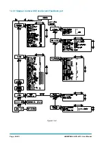
Страница 54: ...Page 54 95 AEMZP0BA EPS AC0 User Manual 12 3 1 Stepper motor with Encoder and Feedback pot Figure 12 2...
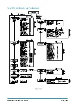
Страница 55: ...AEMZP0BA EPS AC0 User Manual Page 55 95 12 3 2 RTC with Encoder and Feedback pot Figure 12 3...
Страница 56: ...Page 56 95 AEMZP0BA EPS AC0 User Manual 12 3 3 Stepper motor with Encoder and Toggle switch es Figure 12 4...