


Page - 26/95
AEMZP0BA - EPS-AC0 - User Manual
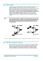
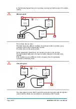
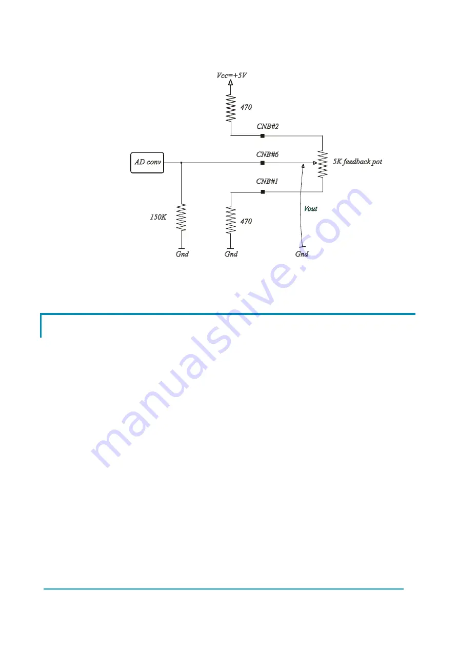
in order it will be possible to detect if a feedback pot connection breaks (see Figure
7-1 below): when Vout overtakes 4.7 V or is lower than 0.3 V an alarm occurs.
Figure 7-1
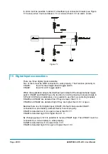
7.5 Digital Inputs connections
There are three digital inputs available.
Two of them must be GND connected to work properly. Their function primarily is:
CNA#3:
Input for the straight-ahead toggle switch
CNA#2:
Input for a 90° toggle switch
When the application adopts the feedback pot instead of the straight-ahead toggle
switch, CNA#3 and CNA#2 have the function to limit the maximum steered angle in
CW and CCW side (in alternative, it is possible to use them as centering request).
CNA#3 and CNA#2 are detected low if they are lower than 1.3 V.
CNA#3 and CNA#2 are detected high if they are higher than 6.6 V or open.
Besides there is a third digital input (CNA#1). Default choice wants CNA#1
connected to a plus battery (default choice) to work properly.
CNA#1 is detected low if it is open or lower than 5.17 V.
CNA#1 is detected high if it is higher than 11 V.
By changing jumper J12 it is possible to reverse CNA#1 logic. Then CNA#1 must be
connected to a minus battery to work properly.
CAN#1 is detected low if it is lower than 1.3 V.
CNA#1 is detected high if it is open or higher than 3.3 V.
Содержание EPS-AC0
Страница 23: ...AEMZP0BA EPS AC0 User Manual Page 23 95 6 2 EPS AC0 Stepper Motor diagram Figure 6 2...
Страница 24: ...Page 24 95 AEMZP0BA EPS AC0 User Manual 6 3 EPS AC0 Twin pot diagram Figure 6 3...
Страница 54: ...Page 54 95 AEMZP0BA EPS AC0 User Manual 12 3 1 Stepper motor with Encoder and Feedback pot Figure 12 2...
Страница 55: ...AEMZP0BA EPS AC0 User Manual Page 55 95 12 3 2 RTC with Encoder and Feedback pot Figure 12 3...
Страница 56: ...Page 56 95 AEMZP0BA EPS AC0 User Manual 12 3 3 Stepper motor with Encoder and Toggle switch es Figure 12 4...