


Page - 60/95
AEMZP0BA - EPS-AC0 - User Manual
FB POT), the steered wheel angle shall be automatically
limited.
-
OFF:
No steered wheel angle limitation, based on the feedback
sensor value, occurs.
Note: the configurations without toggle switches (FB POT only and FB POT &
FB ENC) may use the switches connected to CNA#3 and CNA#2 as CW and
CCW limiting requests. Then, the limitation through the feedback device and the
limitation through the limiting switches are processed with an OR Logic.
5) AUTOCENTERING
(Versions with FEEDBACK DEVICE to OPTION #4 only). When this option is
set ON, the controller performs an automatic centering at key-on and enables
the function to operate an automatic centering on demand. Set
AUTOCENTERING to OFF if the automatic centering function is not required.
6) DIRECTION
GAUGE
Not used.
7) AUX FUNCTION 1
This option sets the steering mode after the feedback sensor has reached the
commanded position (it is used only in closed loop
configurations (i.e. RTC and
automatic centering)).
It can be set one of three:
-
LEVEL 0:
The steering control is always active when a travel demand
is active. The steer control is turned off when the travel
demands are deactivated (after a 3 sec delay).
-
LEVEL 1:
The steering control is alternatively turned off (15 secs long
plus the AUXILIARY TIME) and on (3 secs long).
-
LEVEL 2:
The steering control is alternatively turned off (15 secs long
plus the AUXILIARY TIME) and on (3 secs long) but only
when a travel demand is active.
AUXILIARY TIME is the delay (in secs) the DC standing current takes to arrive
to 0 (see 12.4.4.11).
8) DIAG
MOTOR
TEMP
This option enables the diagnosis of the motor temperature. When it is set On
and the motor temperature overtakes 150°, a MOTOR TEMPERAT alarm
occurs.
The KTY84-130 motor thermal sensor must be connected between CNB#3 and
a minus battery (CNA#13).
9) AUX FUNCTION 11
(only when FEEDBACK DEVICE is OPTION #4).
Option AUX FUNCTION 11
specifies the number of toggle switches (one or two) and defines the
correspondence between the levels of the toggle switches and the steer sector
(quadrant).
Set AUX FUNCTION 11 to the proper Level following table 10-1 (see 10.4). The
proper level must be meant as the one meeting the configuration of the toggle
switches in the first sector (WHEEL ANGLE between 0 and 90 degrees).
10) ENCODER CONTROL
This option specifies if the motor is controlled via encoder or completely
sensorless. Normally it is set OFF. When glitches are heard from the motor, it is
necessary to turn to a sensored control. In this case set ENCODER CONTROL
to On. Then, take care the encoder resolution used in the software (see 4.5.3) is
Содержание EPS-AC0
Страница 23: ...AEMZP0BA EPS AC0 User Manual Page 23 95 6 2 EPS AC0 Stepper Motor diagram Figure 6 2...
Страница 24: ...Page 24 95 AEMZP0BA EPS AC0 User Manual 6 3 EPS AC0 Twin pot diagram Figure 6 3...
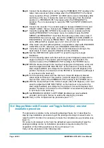
Страница 54: ...Page 54 95 AEMZP0BA EPS AC0 User Manual 12 3 1 Stepper motor with Encoder and Feedback pot Figure 12 2...
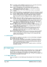
Страница 55: ...AEMZP0BA EPS AC0 User Manual Page 55 95 12 3 2 RTC with Encoder and Feedback pot Figure 12 3...
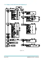
Страница 56: ...Page 56 95 AEMZP0BA EPS AC0 User Manual 12 3 3 Stepper motor with Encoder and Toggle switch es Figure 12 4...