background image

Sondes  

Section 

YSI Incorporated 

Drinking Water Monitoring Systems Operations Manual 

2-68 


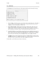
Return to the Main menu using the 

Esc

 key and select 

2-Calibrate

 and then 

4-Free Cl2. 


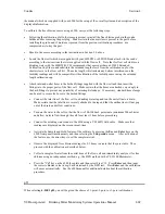
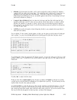
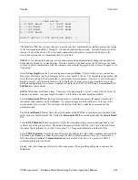
At the prompt, input the independently determined free chlorine value and press 

Enter

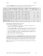
.   A display similar 

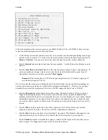
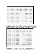
to that shown below will appear on either the computer monitor or the 650 display.   The calibration will 
occur automatically after the countdown on the screen reaches zero.  


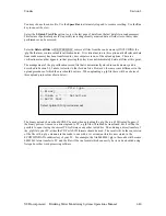
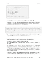
After the warm-up time is complete, the readings just before and just after calibration are displayed.  When 
you press 

Enter

, the screen returns to the Free Chlorine Calibration menu.   


FREE CHLORINE WITH SONDE ATTACHED TO 6500 PROCESS MONITOR 


See 

Appendix G.  Using Your Drinking Water Sonde with a YSI  

6500 Process Monitor

 for enhanced calibration instructions and a detailed description of the Sample and 

Hold feature. 


NOTE CAREFULLY:

 The 6572 free chlorine sensor MUST be calibrated 

in situ

, i.e. in flowing drinking  

water whose free chlorine content has been determined by an independent method.   In many cases, the 
independent method involves the use of the DPD Colorimetric Method as defined in Section 4500-Cl G of


Standard Methods for the Examination of Water and Wastewater

.   Relatively inexpensive colorimeters, 

such as the YSI Models 9000 and 9100 and the Hach Model 5870000, are available for carrying out the 
DPD method to determine the free chlorine in the effluent of the flow cell associated with the 6920DW or 
600DW-B drinking water studies. 
 
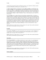
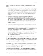
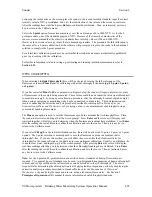
In most cases, the free chlorine sensor should be calibrated AFTER it has been attached to the 6500 Process 
Monitor for 2-3 hours to assure the stabilization of the free chlorine sensor in the flowing tap water.   See 


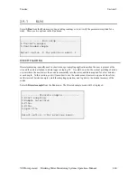
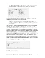
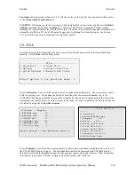
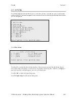
-------------Advanced setup----------- 
1-(*)VT100 emulation                    
2-( )Power up to Menu                   
3-( )Power up to Run                    
4-( )Comma radix                        
5-(*)Auto sleep RS232                   
6-(*)Auto sleep SDI12                   
7-( )Multi SDI12                        
8-( )Full SDI12                         
 
Select option (0 for previous menu): 0 


=================================================================== 
 Temp SpCond    Sal Cl2  Cl2 Chrg    Depth    pH  NH4+ N NO3- N Turbid 
    C  mS/cm    ppt mg/L             feet         mg/L   mg/L    NTU 
------------------------------------------------------------------- 
Stabilizing: 38 


Содержание 600DW-B

Страница 1: ...6 SERIES DRINKING WATER SYSTEMS 600DW B Sonde 6920DW Sonde 650 MDS Display Logger 6500 Process Monitor Environmental Monitoring Systems...

Страница 2: ...ocal YSI representative or YSI Customer Service in Yellow Springs Ohio for a copy of the document See Section 8 Warranty and Service Information for contact information SPECIFICATIONS For general spec...

Страница 3: ......

Страница 4: ...8 3 4 SONDE MENU INTERFACE 3 21 3 5 LOGGING DATA WITH THE 650 3 27 3 6 MANAGING 650 FILES 3 46 3 7 UPLOADING DATA FROM SONDES 3 51 3 8 USING GPS WITH 650 3 51 3 9 USING THE 650 BAROMETER 3 53 3 10 UPG...

Страница 5: ...INFORMATION 8 1 LIMITATIONS OF WARRANTY 8 1 8 2 AUTHORIZED SERVICE CENTERS 8 2 8 3 CLEANING INSTRUCTIONS 8 2 APPENDIX A HEALTH AND SAFETY A 1 APPENDIX B REQUIRED NOTICE B 1 APPENDIX C ACCESSORIES AND...

Страница 6: ...are and sports medicine In the early 1990s YSI launched a line of multi parameter water monitoring systems to address the emerging need to measure non point source pollution Today we have thousands of...

Страница 7: ...and Service Information for contact information 1 3 1 3 1 3 1 3 UNPACKING AND INSPEC UNPACKING AND INSPEC UNPACKING AND INSPEC UNPACKING AND INSPECTION TION TION TION Inspect the outside of the shippi...

Страница 8: ...e free chlorine sensor also requires a different circuit board which is resident in the instrument and this means that DW sondes are not capable of dissolved oxygen measurement and vice versa standard...

Страница 9: ...work best for your application make sure that you have all of the components that are necessary The following list and diagrams provide a few possible configurations Sonde to Lab Computer recommended...

Страница 10: ...tform You will need Sonde Field Cable 6096 Adapter with leads Data Collection Platform 6096 MS 8 Adapter with Flying Leads DCP Field Cable MS 8 Sonde YSI 692 0 Sonde to Portable Computer You will need...

Страница 11: ...ield Cable 650 MDS Display Logger YSI 650 operates on C cells or rechargeable batteries 650 MDS 610 DM Envir onmental Monitoring Systems YS I Field Cable Sonde YS I 69 20 YS I 69 20 MS 8 Sonde to 650...

Страница 12: ...HE FREE CHLORINE PROBE MEMBRANE The 6572 Free Chlorine probe is shipped with a protective cap on the sensor tip which must be removed before proceeding Handle the probe with care It is very important...

Страница 13: ...ove black deposits on the silver electrodes However in extreme cases more sanding may be required to regenerate the original silver surface Rinse the probe tip well with purified water to remove dust...

Страница 14: ...rm a meniscus on the tip of the sensor Remove a white membrane sheet from the package in the 6573 membrane kit as shown in the picture below CAUTION The blue sheets are simply protective spacers and C...

Страница 15: ...t roll the o ring off of the end of the installation tool so that it resides in the o ring groove of the probe Be sure to hold onto the O ring prior to removing the installation tool so that it does n...

Страница 16: ...note that the presence of bubbles under the membrane is also normal and should not affect probe function After installing the membrane either proceed immediately to the sensor activation protocol des...

Страница 17: ...membrane installation techniques which are outline in the manuals for various YSI instruments including standard 6 series sondes utilizing the 6562 Rapid Pulse DO sensor are NOT RECOMMENDED for the fr...

Страница 18: ...emove the ISE port plugs but do not use pliers to tighten the ISE probes Hand tighten only Now refer to the figures below to find the probe locations in your sonde 600DW B SONDE BULKHEAD 6572 Free Chl...

Страница 19: ...ant supplied in the YSI 6570 Maintenance Kit to the O rings on the connector side of each probe that is to be installed CAUTION Make sure that there are NO contaminants between the O ring and the prob...

Страница 20: ...installation tool to tighten the probe With the connectors aligned screw down the probe nut using the long extended end of the probe installation tool Do not over tighten CAUTION Do not cross thread...

Страница 21: ...ernal batteries or can run on external power In addition if you have purchased a YSI 650 MDS display logger or 6500 Process Monitor attaching your sonde to these instruments will allow your sonde to b...

Страница 22: ...connector Insert batteries paying special attention to polarity Labeling on the battery compartment posts describes the orientation It is usually easiest to insert the negative end of battery first an...

Страница 23: ...OVER TIGHTEN 2 3 4 STEP 4 CONNECTING A FIELD CABLE As shown in the picture at left the 6920DW and 600DW B have a sonde mounted cable connector for attachment of cables Two types of cables are availabl...

Страница 24: ...rovides the ability to set up and calibrate your sonde sensors in a similar way to that of a terminal interface to a PC As an alternative to the field cable for interface to a PC you may use a YSI 606...

Страница 25: ...ndows Program Menu For help with the EcoWatch program see Section 4 EcoWatch or use the Help section of the software 2 4 3 ECOWATCH FOR WINDOWS SETUP To setup the EcoWatch software for use with a sond...

Страница 26: ...u rather than the sign may appear when communication is established In this case simply proceed as described below You will not be required to type Menu If you are unable to establish interaction with...

Страница 27: ...ended sample 1 Conductivity 2 DO 1 Run 3 File 2 Calibrate 6 Report 7 Sensor 8 Advanced 1 Discrete sample 3 DO mg L 2 Time 3 Temp C 4 Temp F 1 Date 2 Cond 3 DO 4 ISE1 pH 1 Temp 4 Others 2 Comm Setup 3...

Страница 28: ...either a two or four digit year display If you do not enter the correct year format 8 30 98 for 2 digit 8 30 1998 for 4 digit your entry will be rejected Date time setup 1 m d y 4 4 digit year 2 d m...

Страница 29: ...filename 00003001 7 SDI 12 address 0 8 English 9 Fran ais A Deutsch Select option 0 for previous menu Then press Esc or 0 again to return to the Main menu ENABLING SENSORS To activate the sensors that...

Страница 30: ...enabled as described above 2 That parameter must be activated in the Report Setup menu described below Select Report from the Main menu A Report Setup menu similar to the one shown below will be disp...

Страница 31: ...G ADVANCED SETTINGS Select Advanced from the Main menu The following menu will be displayed Select Setup from the Advanced menu Make sure that other than Auto sleep RS232 all entries are activated or...

Страница 32: ...do not have a chlorophyll probe the last two entries which are relevant only to chlorophyll will not appear When this setup is verified press Esc or 0 to return to the Advanced menu For a detailed exp...

Страница 33: ...the diluted bleach and leave for approximately 60 seconds CAUTION Do not leave the probe in bleach for longer than 1 minute or the break in time for the probe will be excessive Rinse the sensor tip an...

Страница 34: ...calibrator solutions and increases the accuracy of the calibration 5 If you are using laboratory glassware for calibration you do not need to remove the probe guard to rinse and dry the probes between...

Страница 35: ...calibration suspension required An extended calibration cup which is designed to provide both the greatest accuracy and convenience but which requires the use of higher volumes of calibration suspensi...

Страница 36: ...ibration procedures refer to Section 2 9 2 Calibrate To ensure more accurate results you can rinse the calibration cup with water and then rinse with a small amount of the calibration solution for the...

Страница 37: ...isplay will be shown Select 1 SpCond the generally recommended method for calibration of a conductivity sensor the following prompt will appear which calls for your numerical input As noted above the...

Страница 38: ...s contamination of standard solutions with other solutions Make certain that there are no salt deposits around the pH ORP probe particularly if you are employing standards of low conductivity Carefull...

Страница 39: ...the solution Allow at least 1 minute for temperature equilibration before proceeding Press Enter and input the value of the second buffer at the prompt Press Enter and the current values of all enable...

Страница 40: ...ey have show no significant change for approximately 30 seconds press Enter After the second value calibration is complete press Enter to continue Place the proper amount of chilled 1 mg L standard 10...

Страница 41: ...or you MUST use either a modified calibration cup arrangement an extended length calibration cup or laboratory glassware with the probe guard installed for the calibration See section 2 6 1 above for...

Страница 42: ...Clean Optics as shown on the screen to remove any bubbles from the sensor After stabilization is complete press Enter to confirm the calibration and then as instructed press Enter to return to the Cal...

Страница 43: ...ed below Attach inlet and outlet hoses to the barbed fittings supplied with the flow cell and then insert the fittings into the proper ports of the flow cell Make certain that the hoses are attached v...

Страница 44: ...ttached to a YSI 6500 Process Monitor and is outputting data continuously to the 6500 For this mode of operation access the Sonde setup menu of the 6500 as described above and make certain that the Sa...

Страница 45: ...ow readings to be logged to internal memory for 2 3 hours Using the File View command as described in Section 2 9 3 inspect the free chlorine readings and after they are stable proceed with the calibr...

Страница 46: ...eadings will be logged to a single file The communication cable may be disconnected and internal battery power used to operate the sonde Alternatively the sonde may connect via SDI 12 communication to...

Страница 47: ...hout entering a filename the default name NONAME1 will be assigned to your file Whenever you press 1 LOG last sample or 2 LOG ON OFF from the menu NONAME1 will be opened during sampling If this happen...

Страница 48: ...sc or press 0 to exit discrete sampling UNATTENDED SAMPLING Select 2 Unattended Sampling from the Run menu The Unattended sample menu will be displayed Use the following example to understand the unat...

Страница 49: ...in the above example change the Start Time to 18 00 00 Select 4 Duration and set the length of the study in days The default value is 365 days which is longer than most deployments In most cases you...

Страница 50: ...nde by uploading all existing data from the sonde memory to your PC and then deleting them out of the sonde see 3 File from Main Menu You may want to change the batteries for longer battery life You c...

Страница 51: ...rminate when the duration you specified has expired or the batteries are expended If you want to terminate sooner simply select 2 Unattended sample from the Run menu then B Stop logging Select 1 yes a...

Страница 52: ...ta subdirectory of the ECOWWIN directory 6 Click OK After EcoWatch sets up the sonde for the study data transfer will begin at the sample rate you selected The data will be automatically plotted with...

Страница 53: ...e file in the Directory Select 2 Upload to view file lists in memory and upload the data to PC based software Prior to upload a Time window display appears that will allow you to select portions of th...

Страница 54: ...subdirectory Select 4 View File to examine the data in any file currently stored in the sondes flash disk memory You will first view the same screen as viewed in the Directory menu From this menu cho...

Страница 55: ...ipulation capabilities we use the file SAMPLE DAT available on the compact disk that was enclosed with your 6 series sonde This file will be copied to your hard drive during EcoWatch installation and...

Страница 56: ...u items in the top line Some of these functions are specifically related to viewing and manipulating data Next we will examine some of the viewing options VIEWING DATA To look at some of the viewing o...

Страница 57: ...s It may be somewhat awkward to scan the data table in this manner therefore you have the option to turn off the graphical representation and allow the table to fill the window See the figure below No...

Страница 58: ...ctivated The Study function provides useful information about the design of the study including sample interval date time number of samples sensor identification and parameters reported The Statistics...

Страница 59: ...h specific data values in boxes to the left of the displayed graphs as shown in the figure below You can hold down the right mouse button and move the mouse to scan the entire graph that is displayed...

Страница 60: ...are viewed you may add and delete parameters you may change plot appearance using different interval times and different units and you may change the x axis if you prefer a parameter other than date...

Страница 61: ...color You may also change page color trace color and graph background color You may assign a custom 2 line title for the graph and finally you may display 1 trace or 2 per set of axes For display of t...

Страница 62: ...axis This may allow you to discard a noise spike and obtain better resolution of events unrelated to the noise Functions like Autoscale Redraw and Cancel Limits are all used to undo some of the custo...

Страница 63: ...IMPORT EXPORT AND PRINT COMMANDS Under File function in the top line menu you can save a particular presentation version of a data file and give the presentation a customized name For example you mig...

Страница 64: ...iginal data back Under the same Parameters function we have selected Attributes and changed the Average Interval from the default 0 to 60 Since data was collected every 15 minutes the change to a 60 m...

Страница 65: ...ave the custom plot the name 4PARAM to that the presentation can be immediately recalled in the future As you become more familiar with EcoWatch for Windows the plotting analysis and reporting functio...

Страница 66: ...ence with the sonde menus select the sonde icon in EcoWatch for Windows and press Enter See the figure below for the Sonde Menu Flow Chart In the following subsections you will learn about the functio...

Страница 67: ...used in the vertical profiling of a lake or river where the user lowers the sonde incrementally into the water and data acquired for a few minutes at each depth In this section you will learn how to u...

Страница 68: ...number that represents the number of seconds between samples The maximum sample interval is 32767 seconds 9 hours The factory default sample interval is 4 seconds and works best for most discrete samp...

Страница 69: ...1 will be opened during sampling If this happens and you want to restart the file with a different name press 5 Close file and rename the file Select 4 Site to assign a site name with a maximum of 31...

Страница 70: ...our study demands that you start the instrument at the site at 6 00 PM change the Start Time to 18 00 00 Select 4 Duration and set the length of the study in days The default value is 365 days which i...

Страница 71: ...king the above entries the sonde software will automatically estimate the expected battery life and the time it will take for the sonde memory to be filled This information is displayed on the screen...

Страница 72: ...d unless the control of this sensor varies from short term to long term applications For spot sampling it is best to pulse the sensor continuously during the Run mode to attain the most accurate resul...

Страница 73: ...e menu will be displayed Only the enabled parameters will be available for calibration CONDUCTIVITY Select 1 Conductivity to calibrate the conductivity probe and a second menu will offer you the optio...

Страница 74: ...will eliminate any bottom interference on the turbidity readings and will be compatible with calibration of the turbidity sensor using the extended length calibration cup Attach inlet and outlet hose...

Страница 75: ...e sensor MUST be calibrated in situ i e in flowing drinking water whose free chlorine content has been determined by an independent method In many cases the independent method involves the use of the...

Страница 76: ...d very snugly to the barb fittings to prevent any possibility of catastrophic leakage If necessary standard hose clamps can be used to secure the hoses to the barbed fittings Connect the inlet line of...

Страница 77: ...stabilized press Enter to confirm the calibration Then as instructed press Enter again to return to the Calibrate menu Select the 3 point option to calibrate the pH probe using three calibration solut...

Страница 78: ...calibration standards is 1 100 mg L standard at ambient temperature 2 1 mg L standard at ambient temperature and 3 1 mg L standard at a different temperature usually lower than ambient For best result...

Страница 79: ...ting a 6136 turbidity sensor you MUST use either a black bottomed calibration cup arrangement or laboratory glassware with the probe guard installed for the calibration See section 2 6 1 above for det...

Страница 80: ...ng the extractive analysis procedure described for chlorophyll in Methods for the Examination of Water and Wastewater or by carrying out an in situ measurement of chlorophyll using a commercial bencht...

Страница 81: ...either initially calibrate the sensor using a phytoplankton suspension of known chlorophyll content or post calibrate you sensor in a spreadsheet by comparing the fluorescence values obtained in fiel...

Страница 82: ...proceeding with the calibration REESTABILISHING DEFAULT CALIBRATION UNCAL COMMAND If for any reason you want to return to the factory default settings slope and offset for any parameter follow the in...

Страница 83: ...e Circuit Board Serial as the default filename The file can be viewed by following the path File Directory File Details View from the Main sonde menu Pressing 1 View file will show the calibration rec...

Страница 84: ...500 0000 08 23 2001 17 07 50 00003001 Turb A2 1000 000 08 23 2001 17 07 50 00003001 Turb M2 1000 000 08 23 2001 17 07 50 00003001 Chl Offset 0 000000 08 23 2001 17 07 50 00003001 Chl A1 100 0000 08 23...

Страница 85: ...varying sizes To examine the details of each file press the associated number e g 4 for CLRLAKE2 dat and an additional screen will be displayed as shown below that quantifies the time of the deployme...

Страница 86: ...allow you the option to select portions of the logged data to upload You may select 1 Proceed to upload all data logged from the dates and times shown Select 1 Proceed Choose the appropriate file tra...

Страница 87: ...atically stored in sonde memory and is described in Section 2 9 2 above is similar to that for data files However there are some differences in the upload procedure of which the user should be aware W...

Страница 88: ...System setup However you cannot alter date format from this screen In options 4 5 and 6 you can view battery voltage battery life and available free memory in your sonde to help you evaluate whether t...

Страница 89: ...03001 6 GLP filename 00003001 7 SDI 12 address 0 8 English 9 Fran ais A Deutsch Select option 0 for previous menu Select Date time Date time setup 1 m d y 4 4 digit year 2 d m y 5 Date 08 11 98 3 y m...

Страница 90: ...fore if the page length is set to 25 there will be 21 lines of data and one header Any page length less than 5 will result in no header being transmitted Select 4 Instrument ID from the System setup m...

Страница 91: ...PAR2 are associated with a special sonde equipped with a sensor for Photosynthetically Active Radiation PAR which can be purchased from the YSI Massachusetts but is not likely to be useful in drinkin...

Страница 92: ...inute Second 24 hour clock format Temp C Temperature in degrees Celsius Temp F Temperature in degrees Fahrenheit Temp K Temperature in degrees Kelvin SpCond mS cm Specific Conductance in milliSiemens...

Страница 93: ...the sensor using the submenu choices Be certain that the appropriate sensor is enabled in the submenu according to the sonde bulkhead port in which it is physically installed For example if an ammoni...

Страница 94: ...nsors enabled therefore your screen may not be identical to those shown below Select 1 Cal constants to display the calibration constants as shown in the following example Note that values only appear...

Страница 95: ...t checked Cl S 0 195 0 217 to 0 15 Cl A 2 543 Not checked Turb Offset 0 10 to 10 Turb A1 500 0 6 to 1 5 Range is ratio of M1 to A1 Turb M1 500 Turb A2 1000 0 6 to 1 5 Range is ratio of M2 M1 to A2 A1...

Страница 96: ...in either command line or menu mode as set by Power up to Menu If you are using your sonde for Unattended sampling do not activate this mode Activation of this item is NOT recommended except for speci...

Страница 97: ...input your sample interval which defines how often data is transmitted to the 6500 display This new sample interval will automatically become the sample interval for the Run Discrete sample mode of o...

Страница 98: ...be turning the sonde on and off for each sample then you may want to enable this item so that only stable Cl2 data are recorded This item will only appear if the Cl2 sensor is enabled in the Sensors...

Страница 99: ...e effect of unusual or bad readings on the overall data presentation In most cases these spike events are the result of the chance passage of large suspended particles across the probe optics just at...

Страница 100: ...ng descriptions provide additional information about the Data Filter feature 1 Enabled Activating this item will result in data filtering according to the values set in 2 3 and 4 2 Wait for filter If...

Страница 101: ...omes a simple filter with a time constant equal to that set in 3 Time Constant Each time the filter disengages and then re engages this process is repeated Filter engagement and disengagement occurs f...

Страница 102: ...ensor port The 6570 Maintenance Kit can be ordered from any authorized YSI dealer or directly from YSI See Appendix C for details When caring for your sonde remember that the sonde is sealed at the fa...

Страница 103: ...se coated finger to once again lightly go over the mating surface of the o ring DO NOT use excess grease on the o ring or the o ring groove CAUTION Do not over grease the o rings The excess grease may...

Страница 104: ...ion parallel to the platinum electrode located between the two silver electrodes The motion is similar to that used in striking a match Usually 10 15 strokes of the sanding disk are sufficient to remo...

Страница 105: ...ng additional procedure 1 Soak the probe for 10 15 minutes in clean water containing a few drops of commercial dishwashing liquid 2 GENTLY clean the glass bulb and platinum button by rubbing with a co...

Страница 106: ...cant to the O ring before re installation NOTE The ion selective membranes are fragile Be certain to 1 Use only moist high quality lens cleaning tissue for the cleaning procedure not paper towels or o...

Страница 107: ...orine sensor Place enough of deionized distilled or tap water in the calibration cup to cover the sensors insert the sonde into the vessel and seal with the cap O ring to minimize evaporation 2 10 4 P...

Страница 108: ...owever in some cases the sensor may have been irreparably damaged by the dehydration and will require replacement It is also important to remember not to store the pH sensor in distilled or deionized...

Страница 109: ...rated Drinking Water Monitoring Systems Operations Manual 2 102 the sonde replace it with a port plug and store the probe in dry in air to minimize any cosmetic degradation of the probe body and to ma...

Страница 110: ...eb page CE and Australian C Tick Compliance Partnered with a YSI 6 Series sonde the 650 will allow the user to easily Display real time readings from YSI 6 series sondes Log real time sonde data to in...

Страница 111: ...6123 universal charger European power cable British power cable and 6117 battery pack included 6127 Rechargeable Battery Pack Kit with 6116 charger adapter cable 6123 universal charger China Australi...

Страница 112: ...nated deleted as will be described in Section 3 6 5 below For example if a file named TEST is uploaded initially with a memory allocation of 50 kB and then is uploaded at a later time and overwritten...

Страница 113: ...C for data transfer or software upgrade You will need 650 6115 GPS cable User supplied GPS unit with DE 9 cable YSI 6 series sonde with integral or field cable 650 YSI 6 series sonde Integral or field...

Страница 114: ...ions is described in detail in subsequent sections of this manual They are presented here so that your will be able to ascertain if you have all of the parts necessary for your applications You will n...

Страница 115: ...YSI 650 keypad consists of 20 keys as shown in the diagram above There are four function keys up down right and left arrow keys and an alpha numeric keypad The top left key that has a green circle an...

Страница 116: ...lief of the sonde cable Simply open the D ring pass the lanyard loop through the opening and then close the D ring 3 2 5 BATTERIES AN 3 2 5 BATTERIES AN 3 2 5 BATTERIES AN 3 2 5 BATTERIES AND CHARGING...

Страница 117: ...that the gasket is properly installed on the battery lid before reinstallation Reinstall battery lid and tighten the 4 captive screws securely and evenly using a Phillips or slotted screwdriver Do no...

Страница 118: ...ge the batteries continuously for more than 48 hours 4 For long term storage keep your battery pack between the temperatures of 20 C and 30 C and remove it from the 650 case 5 Do not charge your batte...

Страница 119: ...lighter charger contains a 2 ampere fast blow type fuse If the power cord stops working properly unscrew the adapter s cap remove the tip and then pull out and check the fuse See diagram above to rem...

Страница 120: ...The instrument backlight should illuminate the LCD so that the display can be read Pushing the backlight key again will turn the backlight off The backlight will power off automatically after two minu...

Страница 121: ...clock of the 650 or sonde entering calibration parameters for sonde sensors and changing entries such as DO warm up time and optical wiper interval in the Sonde Advanced Sensor submenu You will follow...

Страница 122: ...automatically scroll to the right to prepare for the next alphanumeric input If you make a mistake in the entry simply return to the previous character with the left arrow key and reenter the number...

Страница 123: ...n in the following display Enter the proper number from the keypad for the first date digit Note that when you release the key the cursor moves automatically to the next number Repeat this process unt...

Страница 124: ...to the previous clock setting example where a single press of the numeric 2 key generated the number 2 After completing the above example press the Escape key repeatedly to return to the 650 Main men...

Страница 125: ...in the sonde Instructions for use of these windows are provided in subsequent sections of this manual Note also that there is a disk with rotating segments in the upper right corner of the display wh...

Страница 126: ...barometer reading in units selected by the user in the System setup menu The value is can be used simply as a meteorological parameter or can be used in calibration of sonde dissolved oxygen sensors T...

Страница 127: ...or higher If you encounter difficulties in the upgrade procedures contact YSI Customer Service for advice After reading the above sections and participating in the simple examples provided you should...

Страница 128: ...end the life of your 650 batteries by deactivating this selection Note that the selection MUST BE OFF in order to determine the voltage of the internal batteries of sondes important information for Un...

Страница 129: ...er You can also obtain a barometric pressure value from your local weather service This latter value has usually been corrected to sea level and therefore must be uncorrected before it can be used in...

Страница 130: ...ture of your 6 series sonde software so that you can perform custom setup in the same way that would be possible if the sonde were attached to a PC From the 650 Main Menu select Sonde menu and press E...

Страница 131: ...include Activating Deactivating sensors Setting up the desired Report output Calibrating the sensors Changing the sample interval for Discrete Sample studies Performing file management functions on th...

Страница 132: ...ote that the entire report list can be accessed by continuing to scroll the highlighting block down with the arrow key After activation of salinity in the Report setup of the sonde press the Escape ke...

Страница 133: ...barometric pressure Then press the Enter key and observe the dissolved oxygen reading until stabilization occurs Make sure the Calibrate selection is highlighted in upper window NOTE The current baro...

Страница 134: ...approximately 1 second However if the user chooses to use the Run function from the sonde menu the sample rate can be set to higher values in the Discrete Sample menu This feature will be described i...

Страница 135: ...you want to view Choose Proceed and press Enter to view the entire file or select the portion of the data that you want to view and then select Proceed and press Enter to confirm your selection After...

Страница 136: ...has verified stabilization or as a continuous data stream at a fixed sample interval No matter where or how the user decides to log field data with a 650 sonde system the 650 software plays the key r...

Страница 137: ...The highlighting cursor associated with the logging windows can be moved within a particular window using the up down arrows and toggled from window to window using the left right arrows Note also th...

Страница 138: ...1 INTRODUCTION All YSI 6 series sondes sold since September 1999 have memory present on their internal PCBs In addition all 600XLM 6920 and 6600 sondes have internal memory regardless of the date of p...

Страница 139: ...te and turns the system off 3 5 2 3 EXAMPLE 2 3 5 2 3 EXAMPLE 2 3 5 2 3 EXAMPLE 2 3 5 2 3 EXAMPLE 2 CONTINUOUS LOGGING CONTINUOUS LOGGING CONTINUOUS LOGGING CONTINUOUS LOGGING APPLICATION TO SONDE APP...

Страница 140: ...parameters the user uses the 650 keypad to change the Sample interval from 0 5 seconds to 16 seconds and inputs custom file PROFILE1 and site WEST LAKE designations The user then highlights Start samp...

Страница 141: ...terval is now stored in the sonde memory under the file name PROFILE1 It can be viewed on the 650 display and or uploaded to the 650 memory or directly to a PC by accessing the sonde File menu 3 5 2 4...

Страница 142: ...llowing sections will provide details and examples of the flexibility of logging sonde data to 650 memory The distinction between a simple occasional logging with file and site names entered at the lo...

Страница 143: ...ter and then press Esc to return to the 650 Main menu Once the sample interval is set correctly in the 650 Logging setup menu the user simply highlights the Sonde run selection in the 650 Main menu an...

Страница 144: ...elow Use the arrow keys to scroll horizontally in order to view all of the data Note that using these same basic guidelines data could have been logged at another site on the same day with the user in...

Страница 145: ...site name Files logged to 650 memory under a Single Site Designations will be characterized primarily by the file name but will also have the Site name attached so that it is viewable in either the 6...

Страница 146: ...ate logging studies at various field sites The following discussion and examples should help you understand how to set up site lists for various applications LOGGING OF DATA TO 650 MEMORY FROM SINGLE...

Страница 147: ...the display depending on the position of the cursor To make Site list entries for this application begin by highlighting the Filename position pressing Enter and inputting the file name WEST in this c...

Страница 148: ...ry NOTE If you want to return to the Edit site list display for changes before logging use the RIGHT ARROW KEY to highlight the Configure selection and press Enter The up down arrows will only scroll...

Страница 149: ...smatch screen similar to that for non site list files which will aid in diagnosing the differences in the parameter setup that is preventing the existing file from being appended with new data LOGGING...

Страница 150: ...s WEST and EAST to a single file BLUELAKE To use this list you need to first make certain that the entry Use site list is active in the 650 logging setup Then travel to the WEST site activate the 650...

Страница 151: ...be available for identifying where the data was taken The file BLUELAKE can be examined by use of the 650 File selection In the 650 File menu highlight Directory and press Enter as shown below Then pr...

Страница 152: ...3 5 3 4 EDITING YOUR SITE LIST SITE LIST SITE LIST SITE LIST The 650 software provides powerful tools for editing your site list Actions such as inserting adding new entries deleting existing entries...

Страница 153: ...to 650 memory nor on the data in the files See Section 3 6 below 3 5 4 650 LOGGING 3 5 4 650 LOGGING 3 5 4 650 LOGGING 3 5 4 650 LOGGING CANS AND CAN TS CANS AND CAN TS CANS AND CAN TS CANS AND CAN T...

Страница 154: ...ch correlates with the Site name These lists allow the logging of data from more than one site to the same file Easily view data on the 650 display that has been stored to either sonde or 650 memory E...

Страница 155: ...a i e the file itself will still be present in 650 memory Conversely deleting data files from the 650 memory will not delete the Site Designations from the Site list The management of data stored in t...

Страница 156: ...t the top file PROFILE1 and press Enter to generate a display of the details of this file Press Escape and then highlight the second file DEPLOY1 and press Enter to again display information about the...

Страница 157: ...The data can also be exported from EcoWatch in spreadsheet compatible form if the user prefers this method of data analysis and management In order to carry out the upload of data files to your PC yo...

Страница 158: ...ors or the 650 barometer For files with a dat or txt extension transfer to a PC using the Upload to PC command will proceed automatically and retain the file type that is present in 650 memory For fil...

Страница 159: ...rize the allocation of the used memory space In the example above 6400 bytes are used in defining the memory directory 512 bytes are taken up with accessible files and 0 bytes are taken up in deleted...

Страница 160: ...NOTE The upload MUST be made from the File menu of the sonde not the File menu of the 650 Select the Upload or Quick upload last file and press Enter Then follow the instructions including selection...

Страница 161: ...ther MS 8 connector of the 6115 GPS cable to the MS 8 connector or your sonde cable Attach the male DE 9 connector of the 6115 GPS cable to the mating female connector of your GPS unit Turn on the 650...

Страница 162: ...ptional barometer operates on the strain gauge principle and is located on the internal PCB of the 650 To make certain that the barometer is sensing true atmospheric pressure under conditions of tempe...

Страница 163: ...CHANGING BAR 3 9 3 CHANGING BAROMETER UNITS OMETER UNITS OMETER UNITS OMETER UNITS The 650 offers the user a choice of six commonly used units of barometric pressure which can be displayed in the Sta...

Страница 164: ...stored in 650 memory in units of mm Hg units can easily be converted to readings in mBar after upload 3 10 UPGRADING 650 3 10 UPGRADING 650 3 10 UPGRADING 650 3 10 UPGRADING 650 SOFTWARE SOFTWARE SOF...

Страница 165: ...1 Make sure that cable is connected properly to both 650 and sonde 2 Make certain that you are accessing the upload routine from the sonde File menu and NOT from the 650 File menu Upload of files from...

Страница 166: ...ial Class B Limits for radio frequency emissions specified in EN55011 CISPR11 for Industrial Scientific and Medical laboratory equipment These ferrite assemblies are supplied as part of cable kits To...

Страница 167: ...ing with either the electronic circuitry or the batteries will result in the voiding of the warranty and the compromising of the system performance but more importantly can cause safety hazards which...

Страница 168: ...will cause damage to skin or other tissues If any fluid from the battery pack comes in contact with a user s eyes immediately flush with clean water and consult a physician immediately The alkaline so...

Страница 169: ...d a sharp blow been dropped or otherwise damaged in any way contact YSI Customer Service 10 Do not disassemble charger other than to change the fuse as instructed Replace the part or send it to YSI Pr...

Страница 170: ...nfiguration and for the rechargeable battery pack option Operating Temperature Range for Visible Display 10 to 60 Degrees Celsius Storage Temperature Range 20 to 70 Degrees Celsius Dimensions 9 13 inc...

Страница 171: ...bration temperature Communication Protocol RS 232 to all sondes and for data transfer to PC and for software updates GPS via Y cable NMEA 0183 Standard Backlight Feature 4 LEDs illuminating LCD Keyboa...

Страница 172: ...2 4 1 2 4 1 2 GLOSSARY GLOSSARY GLOSSARY GLOSSARY These are a few of the more commonly used terms used in EcoWatch Term Definition 1 Data display window The window that appears when you open a DAT fil...

Страница 173: ...de or display logger The terminal window is a communication interface with another piece of equipment whereas the Data Display Window is direct interaction with the EcoWatch software 8 Dialog box A di...

Страница 174: ...are displayed to the left of the graph While holding down the right mouse button move to another area on the graph Notice how the measurements change as you move When you release the mouse button the...

Страница 175: ...ata in Comma Delimited CDF format Copy the whole graph page or data from the selection on the table to the clipboard Print the active graph page or table page depending on which one is currently activ...

Страница 176: ...more detailed instructions on calibration of sensors See Section 2 5 Sonde Software Setup for sonde setup 2 Deploy the Sonde For more details see Section 2 Sondes and Section 3 Displays Loggers 3 Ret...

Страница 177: ...dows Section 4 YSI Incorporated Drinking Water Monitoring Systems Operation Manual 4 6 5 Print Your Graph To print the graph open the File menu choose Print Setup or Print to choose exactly how the pr...

Страница 178: ...OGGER LAY LOGGER EcoWatch may be used with various sondes or display loggers To utilize the configuration that will work best for your application make sure that you have all of the components that ar...

Страница 179: ...a that is processed in EcoWatch typically originates in a sonde with batteries and is uploaded to a PC To upload data from a YSI sonde connect the sonde to your PC and open the EcoWatch software Use t...

Страница 180: ...fer the file will be located in the C ECOWWIN DATA subdirectory of your PC hard drive 4 2 4 4 2 4 4 2 4 4 2 4 USING THE GRAPH USING THE GRAPH USING THE GRAPH USING THE GRAPH Once uploaded data can be...

Страница 181: ...to view the study from the beginning limit to the end limit This command can be used on both graphs and data tables Zoom In Click this button to magnify by 20 This command can be used on both graphs a...

Страница 182: ...d which COM port to use for the real time measurements If you do have a default port selected then the program will use that port automatically The number of parameters displayed during real time is s...

Страница 183: ...you want to open This box lists files with the extensions you select in the List Files of Type box List of Files of Type Select the type of file that you want to open dat Sonde binary data file txt p...

Страница 184: ...ent s window as shown below IMPORT IMPORT IMPORT IMPORT With this command you can import common ASCII files into EcoWatch The file will be converted into PC6000 format and again with a DAT extension M...

Страница 185: ...PY COPY TO CLIPBOARD TO CLIPBOARD TO CLIPBOARD TO CLIPBOARD If a graph or table is active then choosing this command will send its contents to the Windows clipboard so that it can be pasted into other...

Страница 186: ...her time and have it look exactly the same as when you saved it This saved display is associated with the data file Up to 9 data displays can be saved per data file When you save a display you will be...

Страница 187: ...ither of two forms a WMF file or a CDF file WMF stands for Windows MetaFile and is a format that describes any image in a way that is independent of the program that generated the image For example yo...

Страница 188: ...File use the Browse button if needed If you want to simply have a report Type listing the data then click Data If you want Statistics minimum maximum average and standard deviation then the statistics...

Страница 189: ...he program will size the graph so that it fits on one page If you choose Exact size then program will print the graph as close as possible to the size that is displayed Maintain Aspect Ratio If you ch...

Страница 190: ...his command to select a printer and a printer connection This command presents the Print Setup dialog box The following options allow you to select the destination printer and its connection Printer S...

Страница 191: ...dditional choices about printing specific to the type of printer you have selected Network Displays a dialog box that allows you to choose a printer if you are on a network PAGE SETUP PAGE SETUP PAGE...

Страница 192: ...indows clipboard so that it can be pasted into other programs This is a normal method of transfer data between different Window programs Copying data to the clipboard replaces the contents previously...

Страница 193: ...TOOLBAR TOOLBAR TOOLBAR Use this command to display and hide the Toolbar which includes buttons for some of the most common commands in EcoWatch such as File Open A check mark appears next to the men...

Страница 194: ...d to display and hide the Table page while viewing a data file Shortcuts Toolbar GRID GRID GRID GRID Turns on or off the gridlines on graphs MARKERS MARKERS MARKERS MARKERS Turns on or off data point...

Страница 195: ...the data the parameters available the logging interval and the beginning and ending times of the sample Shortcuts Toolbar ZOOM IN ZOOM IN ZOOM IN ZOOM IN Enlarges graph or data table whichever is curr...

Страница 196: ...ON COMM UNICATION COMM UNICATION The Comm Communications menu commands let you control your communications settings with sondes modems and other devices Several communication menu options are only ava...

Страница 197: ...andshaking You may choose Xon Xoff or RTS CTS or Both or None Xon Xoff is often referred to as software handshaking and RTS CTS as hardware handshaking If you are using a YSI sonde select Xon Xoff Mod...

Страница 198: ...settings for your modem The Auto Answer setting is included in the dialog for completeness EcoWatch currently does not use Auto Answer Copy to Custom The Copy to Custom button is sometimes helpful in...

Страница 199: ...hen whenever you capture data the program will write to that file without first asking you to confirm If you specify a file but do not select the check box then you will have to confirm that this is t...

Страница 200: ...size and style for any text that appears in the terminal window BACKGROUND COLOR BACKGROUND COLOR BACKGROUND COLOR BACKGROUND COLOR Adjust the background color of the terminal window CAPTURE CAPTURE...

Страница 201: ...is enabled only when the Xmodem or Xmodem 1K protocol has been selected in Port Setup DIAL MODEM DIAL MODEM DIAL MODEM DIAL MODEM If you have specified a default phone number in the Modem tab of the...

Страница 202: ...probe with a wiper then you may want to clean the optics periodically Set that interval in this dialog Autoscaling will keep the trace comfortably on the graph as the measurement changes To Manually...

Страница 203: ...to use this command to indicate only that portion that you are interested in The program will have fewer data points to handle and will respond to your commands quicker Executing this command when mod...

Страница 204: ...d the high and low limits will be dimmed See also the Autoscale command in the Graph menu REDRAW REDRAW REDRAW REDRAW If part of a graph is not displayed it could be because your window is sized too s...

Страница 205: ...in the Selected Parameters list in the order that they were added To rearrange the order highlight the parameter you wish to move and then use the up and down buttons to move it to the desired spot i...

Страница 206: ...age interval to 60 minutes each set of four points will be averaged and then plotted as a single point This feature will not only smooth a graph but will also reduce the amount of data exported that i...

Страница 207: ...ment How do I add TSS to my data file You must have a data set that includes Turbidity data points It is also common to use a 0 to 0 correlation as a base point in these measurements This can be used...

Страница 208: ...SS values by doing a linear interpolation of the Turbidity NTU data and the correlation chart GRAPH GRAPH GRAPH GRAPH The Setup menu Graph submenu has the following commands Font Color Goes to the Fon...

Страница 209: ...tting you specify before you apply it to the document Page Color Goes to the Color Dialog Box where you can change the color of the graph page This is the background for all of the graphs rather than...

Страница 210: ...e you can change the color of the table background color That is the part of the table where the readings appear Highlight Color Goes to the Color Dialog Box where you can change the color of the tabl...

Страница 211: ...lete your template enter the Setup Menu and choose Clear Default Template CLEAR DEFA CLEAR DEFA CLEAR DEFA CLEAR DEFAULT TEMPLATE ULT TEMPLATE ULT TEMPLATE ULT TEMPLATE This command will eliminate a d...

Страница 212: ...apped horizontal tiles TILE VERTICAL TILE VERTICAL TILE VERTICAL TILE VERTICAL Use this command to arrange multiple opened windows side by side ARRANGE ICONS ARRANGE ICONS ARRANGE ICONS ARRANGE ICONS...

Страница 213: ...provide you assistance with this application CONTENTS CONTENTS CONTENTS CONTENTS Offers you a list of the available Help topics USING HELP USING HELP USING HELP USING HELP Use this command for instruc...

Страница 214: ...e ionic species present Because the exact composition of a natural media is usually not known it is best to report a conductivity at a particular temperature e g 20 2 mS cm at 14 o C However in many c...

Страница 215: ...at the site of interest Use the following protocol to determine the conversion factor 1 Determine the specific conductance of a water sample from the site 2 Filter a portion of water from the site 3 C...

Страница 216: ...from the theoretical ORP value This deviation is usually due to a change in the concentration of the KCl in the reference electrode gel To determine whether the sensor is functioning correctly place...

Страница 217: ...ATION AND EFFECT OF TEMPERATURE The software of the sondes calculates pH from the established linear relationship between pH and the millivolt output as defined by a variation of the Nernst equation E...

Страница 218: ...onversion of resistance to temperature is built into the sonde software and accurate temperature readings in degrees Celsius Kelvin or Fahrenheit are provided automatically No calibration or maintenan...

Страница 219: ...y of the sensor is novel consisting of a thin linear platinum cathode placed between two silver rectangles which serve as anode and reference electrodes These sensor changes are necessary to implement...

Страница 220: ...of the sonde at a user selected interval For this mode of operation make certain that the Autosleep RS232 feature is activated in the Advanced Setup menu and that the Chlorine warm up time is set to...

Страница 221: ...lver chloride wire electrode in a custom filling solution The internal solution is separated from the sample medium by a polymer membrane which selectively interacts with nitrate ions When the probe i...

Страница 222: ...nt of the drift will vary depending on the age of the probe the flow rate at the site and the quality of the water For all monitoring studies using ion selective electrodes the user should acquire a f...

Страница 223: ...empirical calibration of the electrode is necessary to establish an accurate slope of the response Typical empirical slopes are 53 58 mV per decade for YSI sensors This slope value is determined by ca...

Страница 224: ...s to sampling applications where only minimal time has elapsed between calibration and field use CALIBRATION AND EFFECT OF TEMPERATURE The ammonium sensor should be calibrated using solutions of known...

Страница 225: ...t which changes in temperature cause no change in voltage Our experience with ISEs indicates that for best accuracy the isopotential point should be determined empirically To do so the user employs a...

Страница 226: ...ze after exposure to pH buffers To accelerate this process soak the sensor in 1000 mg L standard for a few minutes after performing a pH calibration In addition be particularly careful that readings a...

Страница 227: ...e the first calibration point NOTE Before calibrating your 6136 turbidity sensor pay particular attention to the following caution For all calibration procedures you MUST use standards that are based...

Страница 228: ...the use of this feature for all unattended studies The user should determine from experience whether its activation is also appropriate for spot sampling studies at particular sites 5 12 5 12 5 12 5 1...

Страница 229: ...ration from the easy to use YSI chlorophyll system are designed to complement the more accurate but more difficult to obtain results from more traditional methods of chlorophyll determination MEASUREM...

Страница 230: ...is equipped with a mechanical wiper to periodically clean the optical face either by manual or automatic activation With these features the YSI chlorophyll sensor provides the same level of performan...

Страница 231: ...io to obtain the best possible accuracy for your 6025 data 0A variation of this method is to perform a 2 point calibration prior to deployment using a clear water and a dye standard setting apparent c...

Страница 232: ...e YSI chlorophyll sensor with rhodamine WT Enter the calibration value from the table below corresponding to the temperature of the standard WARNING The Chl Tempco factor in the Advanced Sensor menu M...

Страница 233: ...d The YSI 6025 probe is equipped with a mechanical wiper that makes it ideal for unattended applications The wiper can be activated in real time during discrete sampling operations or will function au...

Страница 234: ...in vivo chlorophyll sensors is a portion of a phytoplankton suspension that has been analyzed for chlorophyll by the extractive procedure We recommend the use of this procedure and further recommend t...

Страница 235: ...example the variability of the output can be significant This apparent jumpiness is not observed in dye standards since these are homogeneous solutions containing no suspended matter 4 The sonde chlo...

Страница 236: ...outgassing of the environmental water These bubbles can generally be removed in short term sampling application by simply agitating the sonde manually However for studies longer than a few hours where...

Страница 237: ...repared in the above step to a 1000 mL volumetric and then fill the flask to the top graduation with purified water Mix well to obtain a solution that is 100 ug L 0 10 mg L in water a 1000 1 dilution...

Страница 238: ...l fluorescence a minor interference on rhodamine WT readings from phytoplankton may result Laboratory experiments indicate that a suspension of phytoplankton measured with a YSI 6025 sensor will have...

Страница 239: ...Principles of Operation Section 5 YSI Incorporated Drinking Water Monitoring Systems Operation Manual 5 26...

Страница 240: ...ered remove the free chlorine probe from the sonde and resurface it according to the instructions in Section 2 3 1 of this manual Then install a new membrane and activate the sensor as described in th...

Страница 241: ...N REF Sonde not powered Check 12 vdc source 7 2 Cable connection is loose Check both ends of cable secure connectors Damaged connectors Check pins at both ends insure they are straight dry and clean C...

Страница 242: ...2 7 2 10 2 DO probe has been damaged Replace 6572 probe 8 C Free Chlorine reading unstable or inaccurate Internal failure Return sonde for service 8 Probe requires cleaning Follow probe cleaning proc...

Страница 243: ...or fully 2 6 1 The sensor has been disabled Enable sensor 2 9 5 Water in probe connector Dry connector reinstall probe 2 10 1 Probe has been damaged Replace the 6560 probe 8 C Report output improperly...

Страница 244: ...ne Handshake None For further detail into the sondes RS 232 and SDI 12 implementations see Sections 7 3 and 7 4 respectively With these configurations the Sonde is capable of interfacing to a variety...

Страница 245: ...is a single master multi drop bus and command protocol As many as 10 sensors can be connected to the bus at a time Each sensor is pre assigned a unique address from 0 to 9 Each Sonde is factory set to...

Страница 246: ...nde s software version number 100 for version 1 00 Master aD0 to aD9 Retrieve measurement verifying data Sonde a values CR LF values 33 characters or less This field holds one or more values resulting...

Страница 247: ...onde 1 CR LF Master 1D0 Sonde 1 17 5 12 05 98 7 8 25 6 45 CR LF Master 1D1 Sonde 1 325 10 CR LF After finishing the measurement the Sonde sent a service request to indicate completion The bus master t...

Страница 248: ...ase transportation prepaid to the Authorized Service Center selected by YSI Repair or replacement will be made and the product returned transportation prepaid Repaired or replaced products are warrant...

Страница 249: ...ning Certificate and if in our opinion it represents a potential biological or radioactive hazard our service personnel reserve the right to withhold service until appropriate cleaning decontamination...

Страница 250: ...ate Place the product in a plastic bag to keep out dirt and packing material Use a large carton preferably the original and surround the product completely with packing material Insure for the replace...

Страница 251: ...Warranty and Service Information Section 8 YSI Incorporated Drinking Water Monitoring Systems Operations Manual 8 4...

Страница 252: ...mists and or splashes Get supplier recommendations Provide adequate ventilation Avoid conditions that cause misting or splashing Remove to fresh air Give artificial respiration and get medical attenti...

Страница 253: ...e irritation prolonged or repeated exposure may cause Dermatitis Eye contact may cause irritation or conjunctivitis Ingestion may cause nausea vomiting and diarrhea FIRST AID INHALATION Remove victim...

Страница 254: ...rointestinal irritation and circulatory disturbances FIRST AID INHALATION Remove victim from exposure area to fresh air immediately If breathing has stopped give artificial respiration Keep victim war...

Страница 255: ...antities form the solutions is considered unlikely given the low concentration of lithium and the volumes likely to be handled FIRST AID INHALATION Remove victim from exposure area to fresh air immedi...

Страница 256: ...with large amounts of water approx 15 20 minutes occasionally lifting upper and lower lids Seek medical attention immediately INGESTION Immediately rinse out mouth with large quantities of water If re...

Страница 257: ...TION AVOID INHALATION SKIN CONTACT EYE CONTACT OR INGESTION MAY AFFECT MUCOUS MEMBRANES YSI Turbidity Standard 6073 FIRST AID SKIN CONTACT Remove contaminated clothing Wash affected area with soap or...

Страница 258: ...ation However there is no guarantee that interference will not occur in a particular installation If this equipment does cause interference to radio or television reception which can be determined by...

Страница 259: ...Required Notice Appendix B YSI Incorporated Drinking Water Monitoring Systems Operations Manual B 2...

Страница 260: ...6565 Combination pH ORP Probe 6566 Combination pH ORP Probe Fouling Resistant 6561FG pH Probe with Flat Glass 6565FG Combination pH ORP Probe with Flat Glass 6136 Turbidity Probe wiped 6025 Chlorophy...

Страница 261: ...AGENT CONDUCTIVITY REAGENTS S S S 3161 Calibrator Solution 1 000 uS cm quart 3163 Calibrator Solution 10 000 uS cm quart 3165 Calibrator Solution 100 000 uS cm quart 3167 Calibrator Solution 1 000 uS...

Страница 262: ...battery pack included 6126 Rechargeable Battery Pack Kit with 6116 charger adapter cable 6123 universal charger European power cable British power cable and 6117 battery pack included 6127 Rechargeab...

Страница 263: ...certain conditions such as when the sonde is exposed to certain radio frequency fields If you are concerned with these issues consult the Declaration of Conformity that was enclosed with your instrum...

Страница 264: ...EMC Performance Appendix D YSI Incorporated Drinking Water Monitoring Systems Operations Manual D 2...

Страница 265: ...cm with no depth Weight 1 48 pounds 0 67 kg with batteries Computer Interface RS 232C SDI 12 Internal logging memory size 384 kilobytes 150 000 individual parameter readings Power 4 C size Alkaline Ba...

Страница 266: ...01 mS cm to 0 1 mS cm range dependent Free Chlorine mg L Sensor Type Rapid Pulse Clark type polarographic Range 0 to 3 mg L Accuracy 15 of the reading or 0 05 mg L whichever is greater to maintain acc...

Страница 267: ...ng or 2 mg L whichever is greater Resolution 0 001 mg L N to 1 mg L N range dependent Ammonium Nitrogen Sensor Type Ion selective electrode Range 0 200 mg L N Accuracy 10 of reading or 2 mg L whicheve...

Страница 268: ...Specifications Appendix E YSI Incorporated Drinking Water Monitoring Systems Operations Manual E 4...

Страница 269: ...rine is carried out in the same way Discrete Sampling and Unattended Sampling studies are set up in the same way However there are some key differences from the standard YSI 6 series sondes The sonde...

Страница 270: ...free chlorine by diluting commercial bleach by a factor of 200 For example add 1 mL of commercial bleach to 200 mL of water purified or tap Place the sensor end of the probe in the bleach solution and...

Страница 271: ...n menu and readings will automatically appear on the 650 display Be sure that the Shut off time in the 650 System Setup menu is set to a value of zero so that the 650 maintains interface for the break...

Страница 272: ...orine probe maintenance and potential compromise of pH ORP sensor life or frozen between longer sample intervals RECOMMENDED because of lower frequency of free chlorine probe maintenance and longer pH...

Страница 273: ...ve cap is installed on the connector end of the probe Locate the 6035 Reconditioning Kit which was supplied with your 6572 Free Chlorine Probe Use one of circular sanding disks the 6035 Reconditioning...

Страница 274: ...th a screwdriver style handle as shown in the picture below Thread the nut on the end of the 6572 probe into the base plate as shown in the picture below Place an o ring from the 6573 membrane kit in...

Страница 275: ...low CAUTION The blue sheets are simply protective spacers and CANNOT be used as membranes for the free chlorine sensor As shown in the pictures below lay the membrane on the probe tip that contains th...

Страница 276: ...s shown below right remove the installation tool and make certain that the o ring is centered in the groove on probe end As shown in the picture below use a razor blade or knife to trim away the exces...

Страница 277: ...he sensor activation protocol described above in the Quick Start Guide or store the probe in a beaker of tap water NOT deioinized or distilled water as shown in the picture below to prevent drying out...

Страница 278: ...r should note that the methods recommended for the Teflon installation are not likely to work well for the free chlorine membrane because this membrane cannot be stretched Therefore dissolved oxygen m...

Страница 279: ...ROCESS MONITOR Introduction If you want to output data from your drinking water sonde to a SCADA system in either 4 20 mA or RS 485 Modbus format then you will be required to interface the sonde to a...

Страница 280: ...W sonde with a 6500 and is also designed to be used as a check list for this application In addition this appendix explains in detail the Sample and Hold feature of the DW sonde software which has bee...

Страница 281: ...s no right or wrong way to mount the sonde at the deployment sites One typical method is to simply set the sonde on a bench or other flat surface near the water inlet and drain If a relatively large s...

Страница 282: ...o display the Main menu as shown below Then highlight the 4 20 mA entry press Enter and follow the instructions in Section 3 3 4 of the 6500 manual until all 4 20 mA outputs have been activated and pr...

Страница 283: ...until fully engaged Then attach the other end of the cable MS 8 connector to the corresponding connector on the bottom of the 6500 To make the connection place the cable MS 8 connector over that of th...

Страница 284: ...the sensor readings shown by the 6500 and output to the SCADA which were taken at 10 00 would remain the same even though they might be changing slightly until 10 05 when new sensor readings would be...

Страница 285: ...LL SENSORS EXCEPT FREE CHLORINE WITH THE SAMPLE AND HOLD FEATURE INACTIVE AND THEN CALIBRATE FREE CHLORINE AT A LATER TIME Carry Out Spot Checks of Accuracy and Recalibrate as Necessary You should con...

Страница 286: ...Using Your DW Sonde with a 6500 Process Monitor Appendix G YSI Incorporated Drinking Water Monitoring Systems Operations Manual G 8...

Страница 287: ...ypes of DW sondes are available Two types of sondes shown in the picture below can be purchased for drinking water applications the 6920DW which operates from 8 internal AA batteries and the 600DW B w...

Страница 288: ...ee chlorine sensor has a white body What are the key competitive features of the YSI Drinking Water Sondes Use hardware software and sensors with the exception of free chlorine which have been proven...

Страница 289: ...age tank by simply suspending it from a support into the tank Can I do this with the YSI Drinking Water Sondes The sondes and sensors were not designed for this application but might still provide val...

Страница 290: ...ght be changing slightly until 10 05 when new sensor readings would be output These readings in turn would be frozen until 10 10 when the next readings would be sent to the 6500 The Sample and Hold fe...

Страница 291: ...onsistent with standard reporting convention How does the YSI sensor measure free chlorine The free chlorine sensor operates on the same amperometric principles as the YSI Rapid Pulse dissolved oxygen...

Страница 292: ...chlorine in distribution systems which use ammonia as part of the treatment process and thus have predominantly combined chlorine in their drinking water SENSOR CALIBRATION Is there any difference in...

Страница 293: ...his if you know that there is a high percentage of combined chlorine in your water and you are willing to accept qualitative versus quantitative results in terms of accuracy Remember however that even...

Страница 294: ...Drinking Water Monitoring Systems Operations Manual H 8 Study 2 Study 3 All Data Study 3 Expansion MONITORING OF FREE CHLORINE IN AT OHIO SITE 82 DAY STUDY ONE RECALIBRATION AFTER 7 DAYS OF DEPLOYMEN...

Страница 295: ...ation which are caused by dirty cells during the analysis processes of zeroing the instrument or taking a reading In addition reagents which are out of date and thus have lost their potency could caus...

Страница 296: ...Frequently Asked Questions About YSI Drinking Water Systems Appendix H YSI Incorporated Drinking Water Monitoring Systems Operations Manual H 10...

Страница 297: ......
Страница 298: ...Item 660019 Drawing A660019 Revision A May 2005 1700 1725 Brannum Lane Yellow Springs Ohio 45387 USA 800 765 4974 937 767 7241 FAX 937 767 9320 Website http www ysi com E mail info ysi com...

Отзывы: