YSI 5200A
155
YSI 5200A
154
control several degrees above the desired temperature and the chiller thermo-
stat control several degrees below the desired temperature.
-
Active sensor control timers are reset after systemwide events. Systemwide
events de-energize relays. Example - chiller on time is configured for an eight
(8) minute on time. Energized chiller (control down) relay de-energizes when
5X00 goes into Svr Hold. The chiller on relay had been energized for three (3)
minutes before the Svr Hold occurred. The Svr Hold time is one (1) minute. If
the sensor is reporting control low condition after the service hold time period,
the chiller on time will be for eight (8) minutes and not the remaining five (5)
minutes of the chiller on time prior to entering Svr Hold.
-
Control down relay (chiller) energizes for original “on time” if chiller “on
time” is reconfigured when relay is energized.
Validation Error and Autofix - Set Point Control Only
When an invalid value is entered at the numeric keypad a Validation Error window
displays. An invalid value is either a value outside the range of the sensor system or
a value that breaches other settings within the sensor system. Autofix occurs when
a high or low control value is entered that breaches the set point value. Examples
are provided below:
Low range control value must be < set point value. High range control value must
be > set point value. Low alarm value must be < low control value. High alarm
value must be > high control value.
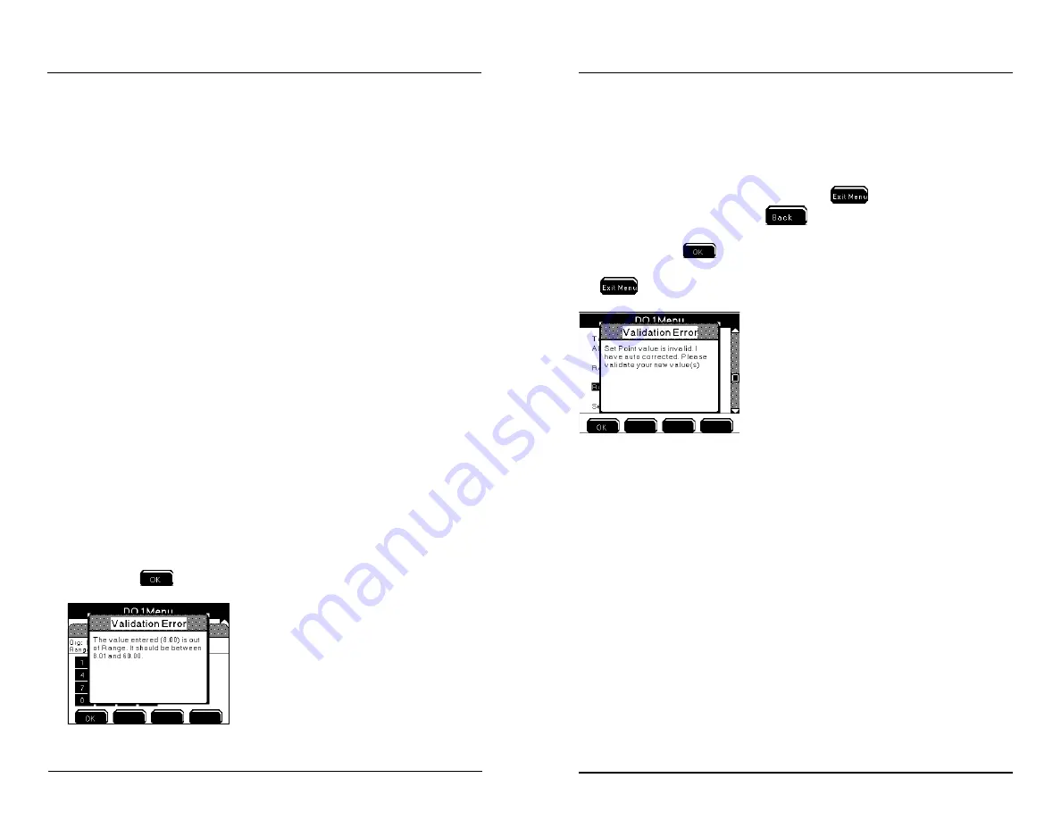
Example - entering “63” for DO set point results in validation error because the
valid range for the DO sensor system is 0.00 to 60.0 mg/l. User must configure
value within valid range. In addition, the value cannot breach respective control
and alarm system values.
Example - configuring set point value of 8.00 mg/L with range low value of 8.00
mg/l results in validation error. Valid set point range is displayed at validation error
display. Press
to return to numeric keypad to enter valid value.
Configuring the 5200A
Autofix occurs when a high or low control value is entered that breaches the set point
value. Autofix changes the high or low control value by one least significant digit
away from the set point value. The set point value is never adjusted.
Example - Entering 8.00 mg/L as the range low value when the set point value is
8.00 mg/L results in an auto fix of the control value. The invalid control value is
displayed at the sensor setup menu. Pressing
is not an option after saving
a value at numeric keypad. Press
from the sensor setup menu to continue
with the autofix. A validation error window is displayed to show that the autofix has
occurred. Press
to return to sensor setup menu. Verify that the autofixed
values are configured for user’s specific application and reconfigure as needed. Press
to save configuration and return to Run Screen.
PID/PWM and PID 4/20mA Control mode
Configure PID/PDW and PID 4/20mA control mode at Sensor Setup menus. (PID
/PWM and PID 4/20mA control modes are also referred to as PID control modes).
PID stands for Proportional, Integral and Derivative. PWM stands for pulse-width
modulation. PID/PWM and PID 4/20mA control modes operate similarily but
use different output to control the control outcome. The difference is that a system
configured in PID/PWM control mode uses a relay as the output control device
and a PID 4/20mA control mode system, instead, drives a 4/20mA output device,
such a valve, to control the system. Both control modes use a complex algothrium
in determining the best way to sustain water system value(s) around a set point
using a relay PID/PWM (on/off) or a value PID 4/20mA. Both control modes can
be used to control an ouput device to maintain a certain water parameter at it’s
set point. Both PID 4/20mA and PID/PWM control modes are feed back control
systems. Three factors determine how these control modes seek to maintain water
system value(s) around a set point. The three factors are:
-the error (distance) from present measurement of input to set point (present time);
-the duration of the error (accumulation of past errors);
-the speed at which the value is approaching the set point (predicts future errors);
Configuring the 5200A


