


JOHNSON CONTROLS
74
FORM 150.67-NM2 (209)
Technical Data
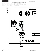
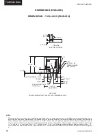
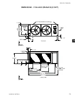
44 5/16"
BASE WIDTH
50 1/16"
49 1/4"
6 3/4"
3 1/4"
3 15/16"
LEFT END
BOTTOM OF PANEL
7/8" TYP.
VIEW B-B
POWER: SINGLE POINT SUPPLY WITH TERMINAL BLOCK
19"
10 3/4"
8 1/2"
2" VICTAULIC CONN (TYP)
LIQUID OUT
B
B
15 1/2"
TO ACCESS PANEL 13 3/8"
2 1/4"
8 5/16"
8 5/16"
2" VICTAULIC CONN (TYP)
LIQUID IN
(2) 3.0 X 1.50
RIGGING HOLES
BOTH ENDS
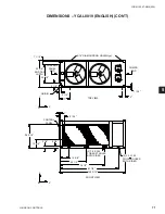
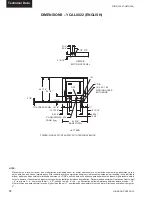
DIMENSIONS – YCAL0028 (ENGLISH)
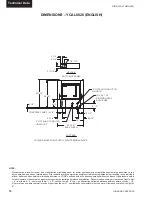
NOTE:
Placement on a level surface of free of obstructions (including snow, for winter operation) or air circulation ensures rated performance, reli-
able operation, and ease of maintenance. Site restrictions may compromise minimum clearances indicated below, resulting in un pre dict able
airfl ow patterns and possible diminished performance. YORK’s unit controls will optimize operation without nuisance high-pres sure safety
cutouts; however, the system designer must consider potential performance degradation. Recommended minimum clearances: front to wall
– 6'; rear to wall – 6'; cooler end to wall – 4'0"; coil end to wall – 6'; top – no obstructions allowed; distance between adjacent units – 10'.
No more than one adjacent wall may be higher than the unit. 1" nominal defl ection isolators (not shown) will increase overall unit height by
6".
Содержание YCAL0019
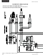
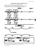
Страница 55: ...FORM 150 67 NM2 209 55 JOHNSON CONTROLS 5 5 ELEMENTARY WIRING DIAGRAM CON T LD12699D...
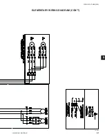
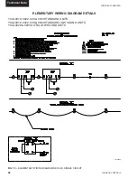
Страница 57: ...FORM 150 67 NM2 209 57 JOHNSON CONTROLS 5 5 ELEMENTARY WIRING DIAGRAM CON T LD12693C...
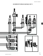
Страница 59: ...FORM 150 67 NM2 209 59 JOHNSON CONTROLS 5 5 ELEMENTARY WIRING DIAGRAM CON T LD 12198...
Страница 61: ...FORM 150 67 NM2 209 61 JOHNSON CONTROLS 5 5 LD12702 ELEMENTARY WIRING DIAGRAM CON T...
Страница 63: ...FORM 150 67 NM2 209 63 JOHNSON CONTROLS 5 5 LD12696 ELEMENTARY WIRING DIAGRAM CON T...
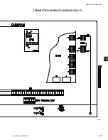
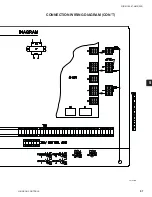
Страница 65: ...FORM 150 67 NM2 209 65 JOHNSON CONTROLS 5 5 CONNECTION WIRING DIAGRAM CON T LD12703B...
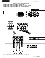
Страница 67: ...FORM 150 67 NM2 209 67 JOHNSON CONTROLS 5 5 CONNECTION WIRING DIAGRAM CON T LD12697B...