
FORM 150.67-NM2 (209)
175
JOHNSON CONTROLS
8
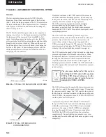
LOAD LIMITING
Load Limiting is a feature that prevents the unit from
loading beyond the desired value. 2 and 4 compressor
units can be load limited to 50%. This would allow only
1 compressor per system to run. 3 and 6 compressor units
can be load limited to 33% or 66%. The 66% limit would
allow up to 2 compressors per system to run, and the
33% limit would allow only 1 compressor per system
to run. Five-compressor units may be load limited to
40% (1 compressor per system runs) or 80% (up to 2
compressors per system) are permitted to run. No other
values of limiting are available.
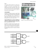
There are two ways to load limit the unit. The
fi
rst is
through remote communication via an ISN. Load limit
stages are sent through YORK Talk on pages 9 and 10
of feature 54. Page 9 is stage 1 load limit and page 10
is stage 2 load limit.
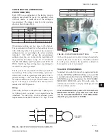
A second method of load limiting the unit is through
closing dry contacts connected to the Load Limit
(CTB1 – Terminals 13 -21). Load limiting involves
closing the Load Limit input with a dry contact. Load
limiting is either 80%, 66% or 50%, depending on the
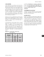
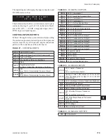
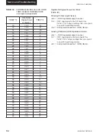
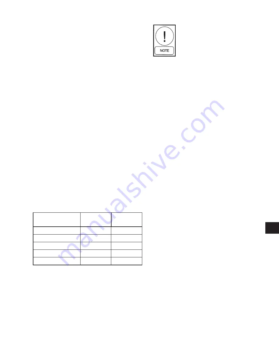
number of compressors on the unit. Table 24 shows
the load limiting permitted for the various number of
compressors. Only Stage 1 is available utilizing a dry
contact.
Simultaneous operation of Remote
Load Limiting and EMS-PWM Tem-
perature Reset (described on following
pages) cannot occur.
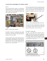
COMPRESSOR RUN STATUS
Compressor run status is indicated by closure of contacts
at CTB2 – terminals 25 to 26 for system 1 and CTB2 –
terminals 27 to 28 for system 2.
ALARM STATUS
System or unit shutdown is indicated by normally-open
alarm contacts opening whenever the unit shuts down on
a unit fault, locks out on a system fault, or experiences
a loss of power to the chiller electronics . System 1
alarm contacts are located at CTB2 – terminals 29 to 30.
System 2 alarm contacts are located at CTB2 – terminals
31 to 32. The alarm contacts will close when conditions
allow the unit to operate, or the fault is reset during a
loss of power, the contacts will remain open until power
is reapplied and no fault conditions exist.
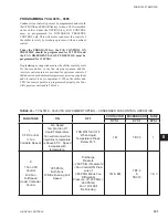
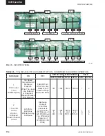
COMPRESSORS
IN UNIT
STAGE 1
STAGE 2
2
50%
-
3
66%
33%
4
50%
-
5
80%
40%
6
66%
33%
TABLE 26 –
COMPRESSOR OPERATION –
LOAD
LIMITING
Содержание YCAL0019
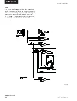
Страница 55: ...FORM 150 67 NM2 209 55 JOHNSON CONTROLS 5 5 ELEMENTARY WIRING DIAGRAM CON T LD12699D...
Страница 57: ...FORM 150 67 NM2 209 57 JOHNSON CONTROLS 5 5 ELEMENTARY WIRING DIAGRAM CON T LD12693C...
Страница 59: ...FORM 150 67 NM2 209 59 JOHNSON CONTROLS 5 5 ELEMENTARY WIRING DIAGRAM CON T LD 12198...
Страница 61: ...FORM 150 67 NM2 209 61 JOHNSON CONTROLS 5 5 LD12702 ELEMENTARY WIRING DIAGRAM CON T...
Страница 63: ...FORM 150 67 NM2 209 63 JOHNSON CONTROLS 5 5 LD12696 ELEMENTARY WIRING DIAGRAM CON T...
Страница 65: ...FORM 150 67 NM2 209 65 JOHNSON CONTROLS 5 5 CONNECTION WIRING DIAGRAM CON T LD12703B...
Страница 67: ...FORM 150 67 NM2 209 67 JOHNSON CONTROLS 5 5 CONNECTION WIRING DIAGRAM CON T LD12697B...