
FORM 150.67-NM2 (209)
35
JOHNSON CONTROLS
4
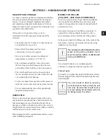
Drain connections should be provided at all low points
to permit complete drainage of the cooler and system
water piping.
A small valve or valves should be installed at the highest
point or points in the chilled water piping to allow any
trapped air to be purged. Vent and drain connections
should be extended beyond the insulation to make them
accessible.
The piping to and from the cooler must be designed to
suit the individual installation. It is important that the
following considerations be observed:
1. The chilled liquid piping system should be laid out
so that the circulating pump discharges directly
into the cooler. The suction for this pump should
be taken from the piping system return line and not
the cooler. This piping scheme is recommended,
but is not mandatory.
2. The inlet and outlet cooler connection sizes are 3”
(YCAL0043 – 0066).
3. A strainer, preferably 40 mesh,
must
be installed
in the cooler inlet line just ahead of the cooler. This
is important to protect the cooler from entrance of
large particles which could cause damage to the
evaporator.
4. All chilled liquid piping should be thoroughly
fl
ushed to free it from foreign material before
the system is placed into operation. Use care not
to
fl
ush any foreign material into or through the
cooler.
5. As an aid to servicing, thermometers and pressure
gauges should be installed in the inlet and outlet
water lines.
6. The chilled water lines that are exposed to outdoor
ambients should be wrapped with supplemental
heater cable and insulated to protect against freeze-
up during low ambient periods, and to prevent
formation of condensation on lines in warm humid
locations.
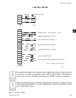
7. A chilled water
fl
ow switch, (either by YORK or
others) MUST be installed in the leaving water
piping of the cooler. There should be a straight
horizontal run of at least 5 diameters on each side
of the switch. Adjust the
fl
ow switch paddle to the
size of the pipe in which it is to be installed (see
manufacturer’s instructions furnished with the
switch). The switch is to be wired to terminals 13
– 14 of CTB1 located in the control panel, as shown
on the unit wiring diagram.
The Flow Switch MUST NOT be used
to start and stop the chiller (i.e. start-
ing and stopping the chilled water
pump). It is intended only as a safety
switch.
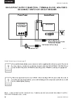
PIPEWORK ARRANGEMENT
The following are suggested pipework arrangements for
single unit installations, for multiple unit installations,
each unit should be piped as shown.
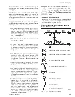
Recommendations of the Building Services
Research Association.
FIG. 7 –
CHILLED LIQUID SYSTEM
ISOLATING VALVE - NORMALLY OPEN
ISOLATING VALVE - NORMALLY CLOSED
FLOW REGULATING VALVE
FLOW MEASUREMENT DEVICE
STRAINER
PRESSURE TAPPING
FLOW SWITCH
FLANGED CONNECTION
LD06597A
LD06596
Содержание YCAL0019
Страница 55: ...FORM 150 67 NM2 209 55 JOHNSON CONTROLS 5 5 ELEMENTARY WIRING DIAGRAM CON T LD12699D...
Страница 57: ...FORM 150 67 NM2 209 57 JOHNSON CONTROLS 5 5 ELEMENTARY WIRING DIAGRAM CON T LD12693C...
Страница 59: ...FORM 150 67 NM2 209 59 JOHNSON CONTROLS 5 5 ELEMENTARY WIRING DIAGRAM CON T LD 12198...
Страница 61: ...FORM 150 67 NM2 209 61 JOHNSON CONTROLS 5 5 LD12702 ELEMENTARY WIRING DIAGRAM CON T...
Страница 63: ...FORM 150 67 NM2 209 63 JOHNSON CONTROLS 5 5 LD12696 ELEMENTARY WIRING DIAGRAM CON T...
Страница 65: ...FORM 150 67 NM2 209 65 JOHNSON CONTROLS 5 5 CONNECTION WIRING DIAGRAM CON T LD12703B...
Страница 67: ...FORM 150 67 NM2 209 67 JOHNSON CONTROLS 5 5 CONNECTION WIRING DIAGRAM CON T LD12697B...