


FORM 150.67-NM2 (209)
141
JOHNSON CONTROLS
7
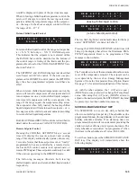
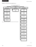
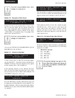
Displays the programmed Low Ambient Cutout.
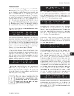
Displays the Leaving Liquid Temp. Cutout
programmed.
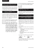
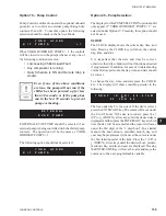
Displays the programmed Fan On Pressure.
Displays the programmed Fan Off Differential.
Displays the programmed High Current Trip Voltage.
Displays the programmed High Current Trip Voltage.
Indicates the Pump Control option is selected.
Displays the Leaving and Return chilled Liquid
Temperature at the time of the fault.
Displays the programmed Setpoint and Range, if
the chiller is programmed for leaving chilled liquid
control.
Displays the programmed Setpoint and Range, if the
chiller is programmed for return chilled liquid control.
Displays the Ambient Temp. at the time of the fault.
Displays the type of Ambient Control; Standard or Low
Ambient.
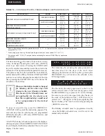
Displays Local or Remote control selection.
Displays the type of chilled liquid control; Leaving or
Return.
Displays the type of lead/lag control; Manual System 1,
Manual System 2 or Automatic. This is only selectable
on 2-system chillers.
Displays the type of fan control; Discharge Pressure or
Ambient and Discharge Pressure.
Displays whether Manual Override was Enabled or
Disabled.
Displays type of Current Feedback utilized.
Displays whether the optional European Soft Start was
installed and selected.
Displays the programmed Discharge Pressure Cutout.
Displays the programmed Suction Pressure Cutout.
L O
W A M
B I E N T T E M P
C U T O U T = X X X . X ° F
S U C T I O N P R E S S U R E
C U T O U T = X X X X P S I G
D I S C H A R G E P R E S S U R E
C U T O U T = X X X X P S I G
L E A D / L A G C O N T R O L
X X X X X X X X
L O C A L / R E M O T E M O D E
X X X X X X X X X
A M B I E N T C O N T R O L
X X X X X X X X X X
L E A V I N G L I Q U I D T E M P
C U T O U T = X X X . X ° F
M A N U A L O V E R R I D E M O D E
X X X X X X X X X
C O N T R O L M O D E
L E A V I N G L I Q U I D
F
A
N
C
O
N
T
R
O
L
D I S C H A R G E P R E S S U R E
F A N C O N T R O L O N
P R E S S U R E = X X X P S I G
C U R R E N T F E E D B A C K
X X X X X X X X X X X X X X X X
S O F T S T A R T
X X X X X X X
F A N D I F F E R E N T I A L
O F F
P R E S S U R E = P S I G
S Y S 2 T R I P V O L T S
= X . X V O L T S
S Y S 1 T R I P V O L T S
= X . X V O L T S
S E T P O I N T = X X X . X ° F
R
A
N
G
E = + / - °
F
A M B I E N T A I R T E M P
= X
X
X
.
X °
F
L C H L T = X X X . X ° F
R C H L T = X X X . X ° F
S E T P O I N T = X X X . X ° F
R
A
N
G
E = +
X
X
.
X °
F
Y
O
R
K H
Y
D
R
O
K I T P
U
M
P
S =
X
Содержание YCAL0019
Страница 55: ...FORM 150 67 NM2 209 55 JOHNSON CONTROLS 5 5 ELEMENTARY WIRING DIAGRAM CON T LD12699D...
Страница 57: ...FORM 150 67 NM2 209 57 JOHNSON CONTROLS 5 5 ELEMENTARY WIRING DIAGRAM CON T LD12693C...
Страница 59: ...FORM 150 67 NM2 209 59 JOHNSON CONTROLS 5 5 ELEMENTARY WIRING DIAGRAM CON T LD 12198...
Страница 61: ...FORM 150 67 NM2 209 61 JOHNSON CONTROLS 5 5 LD12702 ELEMENTARY WIRING DIAGRAM CON T...
Страница 63: ...FORM 150 67 NM2 209 63 JOHNSON CONTROLS 5 5 LD12696 ELEMENTARY WIRING DIAGRAM CON T...
Страница 65: ...FORM 150 67 NM2 209 65 JOHNSON CONTROLS 5 5 CONNECTION WIRING DIAGRAM CON T LD12703B...
Страница 67: ...FORM 150 67 NM2 209 67 JOHNSON CONTROLS 5 5 CONNECTION WIRING DIAGRAM CON T LD12697B...