


JOHNSON CONTROLS
152
FORM 150.67-NM2 (209)
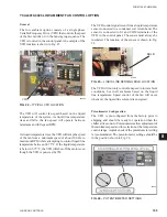
Unit Controls
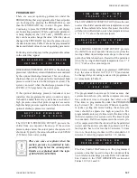
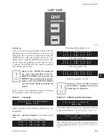
Option 4 – Ambient Control Type:
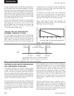
The low ambient cutout is adjustable from 25 °F to 60 °F
(-3.9 °C to 15.6 °C).
or
The low ambient cutout is programmable down to 0 °F
(-17.8 °C).
A low ambient kit MUST be installed for
this option to be chosen. If the kit is NOT installed,
and low ambient is selected, low pressure faults and
compressor damage may occur.
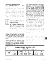
Option 5 – Local/Remote Control Type:
When programmed for LOCAL, an ISN or RCC control
can be used to monitor only. The micro panel will operate
on locally programmed values and ignore all commands
from remote devices, or through the RS-485 inputs. The
chiller will communicate and send data to the remote
monitoring devices.
or
This mode should be selected when an ISN or RCC
control is to be used to control the chiller. This mode
will allow the ISN to control the following items:
Remote Start/Stop, Cooling Setpoint, Load Limit, and
History Buffer Request. If the unit receives no valid
ISN transmission for 5 minutes, it will revert back to
the locally programmed values.
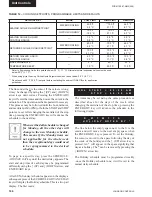
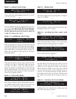
Option 6 – Unit Control Mode:
Unit control is based on return chilled liquid temp. Re-
turn Chilled Liquid Control can only be selected on units
that have 4 to 6 compressors (dual system units).
or
L O C A L / R E M O T E M O D E
R
E
M
O
T
E
A M B I E N T C O N T R O L
L
O
W
A
M
B
I
E
N
T
L O C A L / R E M O T E M O D E L
L O C A L
C O N T R O L M O D E
R
E
T
U
R
N L I
Q
U
I
D
C O N T R O L M O D E
L E A V I N G L I Q U I D
A M B I E N T C O N T R O L
S T A N D A R D
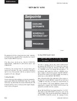
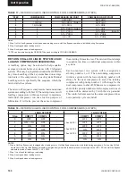
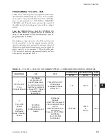
Option 7 – Display Units:
This mode displays system operating values in Imperial
units of °F or PSIG.
or
This mode displays system operating values in Scienti
fi
c
International Units of °C or barg.
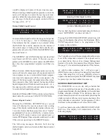
Option 8 – Lead/Lag Type (two system units
only):
SYS 1 selected as lead compressor. SYS 1 lead option
MUST be chosen if Hot Gas Bypass is installed.
or
SYS 2 selected as lead compressor.
or
Lead/lag between systems may be selected to help
equalize average run hours between systems on
chillers with 2 refrigerant systems. Auto lead/lag
allows automatic lead/lag of the two systems based
on an average run hours of the compressors in each
system. A new lead/lag assignment is made whenever
all compressors shut down. The micro will then assign
the “lead” to the system with the shortest average run
time.
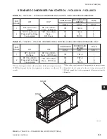
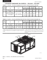
Option 9 – Condenser Fan Control Mode:
Condenser fans are controlled by discharge pressure
only. This mode must be chosen.
or
D I S P L A Y U N I T S
I
M
P
E
R
I
A
L
D I S P L A Y U N I T S
S I
L E A D / L A G C O N T R O L
M A N U A L S Y S 1 L E A D
L E A D / L A G C O N T R O L
M A N U A L S Y S 2 L E A D
L E A D / L A G C O N T R O L
A
U
T
O
M
A
T I
C
F
A
N
C
O
N
T
R
O
L
D I S C H A R G E P R E S S U R E
Содержание YCAL0019
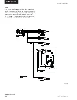
Страница 55: ...FORM 150 67 NM2 209 55 JOHNSON CONTROLS 5 5 ELEMENTARY WIRING DIAGRAM CON T LD12699D...
Страница 57: ...FORM 150 67 NM2 209 57 JOHNSON CONTROLS 5 5 ELEMENTARY WIRING DIAGRAM CON T LD12693C...
Страница 59: ...FORM 150 67 NM2 209 59 JOHNSON CONTROLS 5 5 ELEMENTARY WIRING DIAGRAM CON T LD 12198...
Страница 61: ...FORM 150 67 NM2 209 61 JOHNSON CONTROLS 5 5 LD12702 ELEMENTARY WIRING DIAGRAM CON T...
Страница 63: ...FORM 150 67 NM2 209 63 JOHNSON CONTROLS 5 5 LD12696 ELEMENTARY WIRING DIAGRAM CON T...
Страница 65: ...FORM 150 67 NM2 209 65 JOHNSON CONTROLS 5 5 CONNECTION WIRING DIAGRAM CON T LD12703B...
Страница 67: ...FORM 150 67 NM2 209 67 JOHNSON CONTROLS 5 5 CONNECTION WIRING DIAGRAM CON T LD12697B...