
JOHNSON CONTROLS
160
FORM 150.67-NM2 (209)
Unit Operation
RETURN CHILLLED LIQUID SYSTEM LEAD/
LAG AND COMPRESSOR SEQUENCING
A lead/Lag option may be selected to help equalize
average run hours between systems with 2 re
fi
gerant
systems. This may be programmed under the OPTIONS
key. Auto Lead/Lag of the 2 systems based on average
run hours of the compressors in each system. Manual
Lead/Lag selects speci
fi
cally the sequence which the
micro starts the systems.
The micro will sequence compressors load and unload
systems according to Table 18. The microprocessor will
lead/lag compressors within each circuit to maximize
individual compressor run time for the purpose of
lubrication. It will also prevent the same compressor
from starting 2 times in a row. The micro will not attempt
to equalize run time on individual compressors within
a system.
Each compressor in a system will be assigned an
arbitrary number 1, or 2. The non-running compressor
within a system with the lowest priority number will
always be the next compressor to start. The running
compressor with priority number 1 will always be the
next compressor to shut off. Whenever a compressor is
shut off, the priority numbers of all compressors in each
system will be decreased by 1 with the wrap around.
This control scheme assures the same compressor does
not repeatedly cycle on and off.
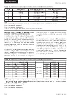
Notes:
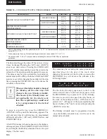
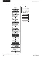
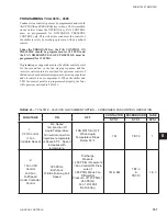
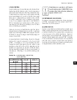
1. Step 1 is Hot Gas Bypass and is skipped when loading occurs. Hot Gas Bypass operation is inhibited during Pumpdown.
2. Step 3 is skipped when loading occurs.
3. Step 4 is skipped when unloading occurs.
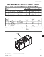
TABLE 17 –
RETURN CHILLED LIQUID CONTROL FOR 4 COMPRESSORS (6 STEPS)
* STEP can be viewed using the OPER DATA key and scrolling to COOLING DEMAND.
*STEP
COMPRESSOR
COMPRESSOR ON POINT
COMPRESSOR OFF POINT
0
0 SETPOINT
SETPOINT
1
1 W/HGB
SP + CR/8 (Note 1)
SETPOINT
2
1 NO HGB
SP + CR/4
SP + CR/8
3
2
SP + 2*CR/4 (Note 2)
SP + CR/4
4
2
SP + 2*CR/4
SP + CR/4
(Note 3)
5
3
SP + 3*CR/4
SP + 2*CR/4
6
4
SP + CR
SP + 3*CR/4
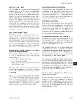
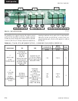
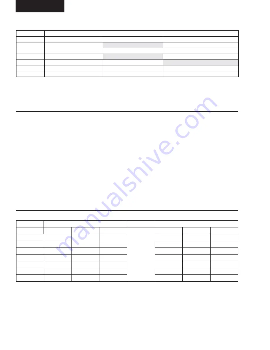
LEAD SYSTEM
LAG SYSTEM
Step
COMP 1
COMP 2
-
See NOTE 1
See NOTE 2
See NOTE 3
COMP 1
COMP 2
-
0
OFF
OFF
-
OFF
OFF
-
1
ON + HG
OFF
-
OFF
OFF
-
2
ON
OFF
-
OFF
OFF
-
3
ON
OFF
-
ON
OFF
-
4
ON
ON
-
OFF
OFF
-
5
ON
ON
-
ON
OFF
-
6
ON
ON
-
ON
ON
-
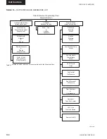
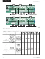
NOTES
1. Step is Hot Gas Bypass and is skipped when loading occurs. Hot Gas Bypass operation is inhibited during pumpdown. For Leaving Chilled
Liquid Control the Hot Gas Bypass solenoid is energized only when the lead compressor is running and the LWT < SP, the Hot Gas Bypass
solenoid is turned off when the LWT > SP + CR/2.
1. Step 1 is not used for loading or unloading.
2. Step 3 is skipped when loading occurs.
3. Step 4 is skipped when unloading occurs.
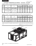
TABLE 18 –
RETURN CHILLED LIQUID CONTROL FOR 4 COMPRESSORS (6 STEPS)
Содержание YCAL0019
Страница 55: ...FORM 150 67 NM2 209 55 JOHNSON CONTROLS 5 5 ELEMENTARY WIRING DIAGRAM CON T LD12699D...
Страница 57: ...FORM 150 67 NM2 209 57 JOHNSON CONTROLS 5 5 ELEMENTARY WIRING DIAGRAM CON T LD12693C...
Страница 59: ...FORM 150 67 NM2 209 59 JOHNSON CONTROLS 5 5 ELEMENTARY WIRING DIAGRAM CON T LD 12198...
Страница 61: ...FORM 150 67 NM2 209 61 JOHNSON CONTROLS 5 5 LD12702 ELEMENTARY WIRING DIAGRAM CON T...
Страница 63: ...FORM 150 67 NM2 209 63 JOHNSON CONTROLS 5 5 LD12696 ELEMENTARY WIRING DIAGRAM CON T...
Страница 65: ...FORM 150 67 NM2 209 65 JOHNSON CONTROLS 5 5 CONNECTION WIRING DIAGRAM CON T LD12703B...
Страница 67: ...FORM 150 67 NM2 209 67 JOHNSON CONTROLS 5 5 CONNECTION WIRING DIAGRAM CON T LD12697B...