


FORM 150.67-NM2 (209)
137
JOHNSON CONTROLS
7
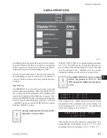
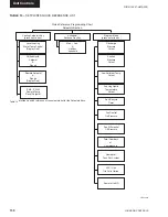
PWM TEMP – EMS temperature reset
* R e f e r t o t h e s e c t i o n o n O P E R AT I N G
CONTROLS.
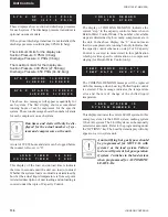
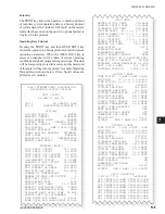
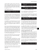
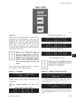
If the micro is programmed for CURRENT FEEDBACK
ONE PER UNIT under the OPTIONS Key, the display
will show up as the
fi
rst display prior to the SYS 1
displays. Total chiller current is displayed as shown
below:
If the micro is programmed for CURRENT FEEDBACK
NONE, no current display will appear.
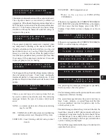
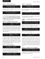
The preceding
fi
ve messages will appear sequentially,
fi
rst for system 1, then for system 2.
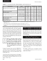
The
fi
rst message indicates the system and the associated
compressors which are running.
The second message indicates the system run time in
days – hours – minutes – seconds. Please note that this
is not accumulated run time but pertains only to the
current system cycle.
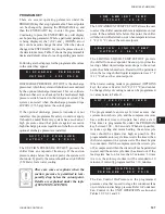
The third message indicates the system, and whether the
liquid line solenoid or EEV pilot solenoid and hot gas
solenoid are being turned on by the microboard. Please
note that hot gas is not available for system 2, so there
is no message pertaining to the hot gas solenoid when
system 2 message is displayed.
The fourth message indicates the stage of condenser fan
operation that is active.
E V A P O R A T O R H E A T E R
S T
A
T
U
S I
S =
X
X
X
This display indicates the status of the evaporator heater.
The evaporator heater is controlled by ambient air
temperature. When the ambient temperature drops below
40 °F the heater is turned on. When the temperature rises
above 45 °F the heater is turned off. An under voltage
condition will keep the heater off until full voltage is
restored to the system.
The evaporator pump dry contacts are energized when
any compressor is running, or the unit is not OFF on
the daily schedule and the unit switch is on, or the unit
has shutdown on a Low Leaving Chilled Liquid fault.
However, even if one of above is true, the pump will not
run if the micro panel has been powered up for less than
30 seconds or if the pump has run in the last 30 seconds
to prevent pump motor overheating.
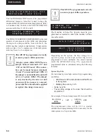
The Evaporator Pump Total Run Hours display indicates
the total pump run hours. Total hours continually
increments similar to Compressor Run Hours. If dual
pumps are
fi
tted, run hours indicates total hours on both
pumps.
There are several types of remote systems that can
be used to control or monitor the unit. The following
messages indicate the type of remote control mode
active:
NONE – no remote control active. Remote monitoring
may be via ISN.
ISN – YORK Talk via ISN allows remote load limiting
and temperature reset through an ISN system.
LOAD LIM – Load limiting enabled using contact
closure.
A C T I V E R E M O T E C T R L
N O N E
U N I T
A M P S = 5 4 . 0
V O L T S = 1 . 2
S Y S X R U N
T I M E
X X - X X - X X - X X D - H - M - S
S Y S X C O
M P S T A T U S
1 = X X X 2 = X X X 3 = X X X
S Y S X L L S V I S O N
H O T G A S S O L I S O F F
S Y S X
A M P S = 3 6 . 0
V O L T S = 0 . 8
S Y S X
F A N S T A G E 3
E V A P
P U M P T O T A L R U N
H
O
U
R
S =
X
X
X
X
X
E V
A
P
O
R
A
T
O
R
W
A
T
E
R
P U
M
P S
T
A
T
U
S =
X
X
X
X
Содержание YCAL0019
Страница 55: ...FORM 150 67 NM2 209 55 JOHNSON CONTROLS 5 5 ELEMENTARY WIRING DIAGRAM CON T LD12699D...
Страница 57: ...FORM 150 67 NM2 209 57 JOHNSON CONTROLS 5 5 ELEMENTARY WIRING DIAGRAM CON T LD12693C...
Страница 59: ...FORM 150 67 NM2 209 59 JOHNSON CONTROLS 5 5 ELEMENTARY WIRING DIAGRAM CON T LD 12198...
Страница 61: ...FORM 150 67 NM2 209 61 JOHNSON CONTROLS 5 5 LD12702 ELEMENTARY WIRING DIAGRAM CON T...
Страница 63: ...FORM 150 67 NM2 209 63 JOHNSON CONTROLS 5 5 LD12696 ELEMENTARY WIRING DIAGRAM CON T...
Страница 65: ...FORM 150 67 NM2 209 65 JOHNSON CONTROLS 5 5 CONNECTION WIRING DIAGRAM CON T LD12703B...
Страница 67: ...FORM 150 67 NM2 209 67 JOHNSON CONTROLS 5 5 CONNECTION WIRING DIAGRAM CON T LD12697B...