


JOHNSON CONTROLS
142
FORM 150.67-NM2 (209)
Unit Controls
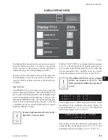
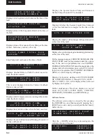
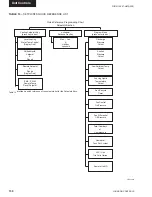
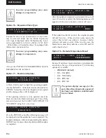
Displays which system is in the lead at the time of the
fault.
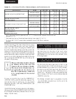
Displays status of the Evaporator Heater at the time of
the fault.
Displays status of Evaporator Water Pump at the time
of fault. Status may read on, off or trip.
Evap Pump total run hours at the time of fault.
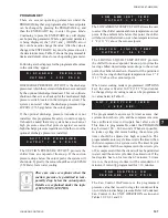
Displays whether Remote Chiller Control was active
when the fault occurred.
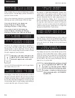
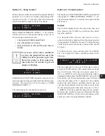
This is only displayed when the Current Feedback
Option is one per unit.
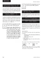
Displays which Compressors were running in the system
when the fault occurred.
Displays the system run time when the fault occurred.
Displays the system Suction and Discharge Pressure of
the time of the fault.
Displays the System Suction Temp and Saturated
Suction Temp when an EEV is installed.
Displays whether the System Liquid Line Solenoid
or Hot Gas Solenoid was energized at the time of the
fault.
Displays the number of Fan Stages in the system active
at the time of the fault.
Displays the system Amperage (calculated approximately)
at the time of the fault.
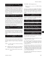
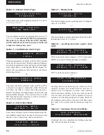
For this message to appear, CURRENT FEEDBACK ONE
PER SYSTEM must be programmed under the options
key. If the micro is programmed as one CURRENT
FEEDBACK ONE PER UNIT under the program key, the
display will be the
fi
rst display prior to the SYS 1 info. If
the micro is programmed for CURRENT FEEDBACK
NONE, no current display will appear.
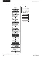
Displays for System 1 starting with SYS X NUMBER
OF COMPS RUNNING X through SYS X AMPS =
XXX.X VOLTS = X.X will be displayed
fi
rst, followed
by displays for System 2.
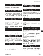
Further explanation of the above displays is covered
under the STATUS, OPER DATA, COOLING
SETPOINTS, PROGRAM, and OPTIONS keys.
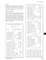
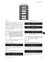
Software Version
The software version may be viewed by
fi
rst pressing
the HISTORY key and then repeatedly pressing the
↓
(DOWN) arrow key until you scroll past the
fi
rst history
buffer choice.
After the
↓
(DOWN) arrow key is pressed again, the
software version will appear.
E V A P O R A T O R H E A T E R
S T
A
T
U
S I
S X
X
X
A C T I V E R E M O T E C T R L
X
X
X
X
U N I T A C T U A L A M P S
=
X
X
X
.
X A
M
P
S
S Y S X S P = X X X X P S I G
D
P = X
X
X
X P
S
I
G
S Y S X R U N T I M E
X X - X X - X X - X X D - H - M - S
S Y S X C O
M P S T A T U S
1 = X X X 2 = X X X 3 = X X X
S Y S X L L S V I S X X X
H O T G A S S O L I S X X X
S Y S X S U C T = X X X . X ° F
S A T S U C T = X X X . X ° F
S Y S X F A N S T A G E X X X
S Y S X
A
C T U A L A M P S
=
X
X
X
.
X A
M
P
S
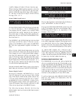
D I S P L A Y S A F E T Y S H U T -
D O
W
N N O . 1 ( 1 T O 6 )
C
O
N
T
R
O
L
C.
M
X
X.
Z
Z.
Y
Y
I /
O
C.
M
X
X.
1
8.
Y
Y
L
E
A
D S
Y
S
T
E
M I
S
S
Y
S
T
E
M N
U
M
B
E
R X
E V A P O R A T O R W A T E R
P U
M
P S
T
A
T
U
S X
X
X
X
E V A P P U M P T O T A L R U N
H
O
U
R
S =
X
X
X
X
Содержание YCAL0019
Страница 55: ...FORM 150 67 NM2 209 55 JOHNSON CONTROLS 5 5 ELEMENTARY WIRING DIAGRAM CON T LD12699D...
Страница 57: ...FORM 150 67 NM2 209 57 JOHNSON CONTROLS 5 5 ELEMENTARY WIRING DIAGRAM CON T LD12693C...
Страница 59: ...FORM 150 67 NM2 209 59 JOHNSON CONTROLS 5 5 ELEMENTARY WIRING DIAGRAM CON T LD 12198...
Страница 61: ...FORM 150 67 NM2 209 61 JOHNSON CONTROLS 5 5 LD12702 ELEMENTARY WIRING DIAGRAM CON T...
Страница 63: ...FORM 150 67 NM2 209 63 JOHNSON CONTROLS 5 5 LD12696 ELEMENTARY WIRING DIAGRAM CON T...
Страница 65: ...FORM 150 67 NM2 209 65 JOHNSON CONTROLS 5 5 CONNECTION WIRING DIAGRAM CON T LD12703B...
Страница 67: ...FORM 150 67 NM2 209 67 JOHNSON CONTROLS 5 5 CONNECTION WIRING DIAGRAM CON T LD12697B...