
FORM 150.67-NM2 (209)
169
JOHNSON CONTROLS
8
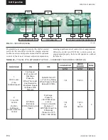
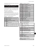
CONFIGURATION (JUMPERS AND
POTENTIOMETERS)
Each VFD is pre-con
fi
gured at the factory prior to
shipping and should be ready for operation when
it arrives onsite. A quick check of the settings is
recommended. The jumpers must be in the positions
shown in the following Tabl
e.
VFD JUMPERS
J2
REMOVE
—
J3
IN
—
J4
REMOVE
—
J5
IN
—
J6
IN
—
J7
IN
—
J8
IN
—
J9
IN FOR 60 HZ
REMOVE FOR 50 HZ
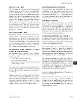
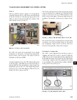
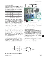
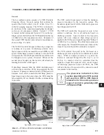
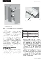
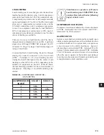
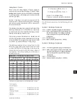
Potentiometer settings are also preset at the factory.
The potentiometers should be in the positions shown
in the following table. The pots do not have numerical
settings and are set according to the arrow positions
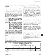
indicated. DO NOT change the potentiometer
settings unless they do not match the positioning of
the potentiometers shown in Fig. 29. P1 should be
full CW (292 PSIG) and P2 should be full CCW (32
PSIG).
Modifying these settings may cause damage to
the chiller or control problems.
The P1 pot sets the setpoint which is the top end of the
control range. This setting is the discharge pressure at
which the fan will be operating at full speed. The P2
pot sets the range. This is the range of pressure where
the VSD modulates the fan speed from 0 RPM to full
speed. The range is subtracted from the setpoint to
calculate the 0 RPM pressure.
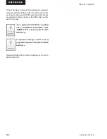
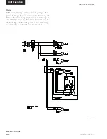
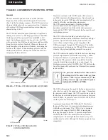
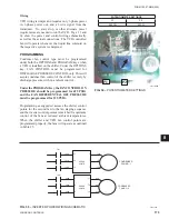
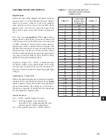
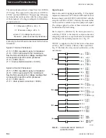
Wiring
VFD wiring is simple and requires only 3-phase power
in, 3-phase power out, and a 2-wire signal from the
transducer. No start, stop, or other alternate power
requirements are needed to run the VFD. Fig’s 28 and
29 show the power and control wiring schematically
as well as the actual connections. The VFD controlled
fan will operate whenever the liquid line solenoid on
the respective system is energized
P1
P2
P1
P2
POTENTIOMETER SETTINGS
P1
P2
292 PSI
32 PSI
FIG. 29 –
POTENTIOMETER SETTINGS
LD11300A
FIG. 28 –
INVERTER POWER WIRING SCHEMATIC
LD11301a
150A
L1
T1
150
151A
L2
T2
151
152A
L3
T3
152
CONDENSER
FAN NO. 1
SPEED
CONTR.
7M
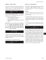
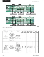
YCAL0033 PROGRAMMING
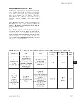
Condenser fan control type must be programmed under
both the OPTIONS and PROGRAM keys when an VFD
is installed on the chiller. Under the OPTIONS key, FAN
CONTROL must be programmed for DISCHARGE
PRESSURE CONTROL only. This will assure the
condenser fan control is solely by discharge pressure
with no ambient control.
Under the PROGRAM key, the FAN CONTROL ON
PRESSURE should be programmed for 425 PSIG
and the FAN DIFFERENTIAL OFF PRESSURE
should be programmed for 125 PSIG.
Содержание YCAL0019
Страница 55: ...FORM 150 67 NM2 209 55 JOHNSON CONTROLS 5 5 ELEMENTARY WIRING DIAGRAM CON T LD12699D...
Страница 57: ...FORM 150 67 NM2 209 57 JOHNSON CONTROLS 5 5 ELEMENTARY WIRING DIAGRAM CON T LD12693C...
Страница 59: ...FORM 150 67 NM2 209 59 JOHNSON CONTROLS 5 5 ELEMENTARY WIRING DIAGRAM CON T LD 12198...
Страница 61: ...FORM 150 67 NM2 209 61 JOHNSON CONTROLS 5 5 LD12702 ELEMENTARY WIRING DIAGRAM CON T...
Страница 63: ...FORM 150 67 NM2 209 63 JOHNSON CONTROLS 5 5 LD12696 ELEMENTARY WIRING DIAGRAM CON T...
Страница 65: ...FORM 150 67 NM2 209 65 JOHNSON CONTROLS 5 5 CONNECTION WIRING DIAGRAM CON T LD12703B...
Страница 67: ...FORM 150 67 NM2 209 67 JOHNSON CONTROLS 5 5 CONNECTION WIRING DIAGRAM CON T LD12697B...