


JOHNSON CONTROLS
144
FORM 150.67-NM2 (209)
Unit Controls
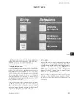
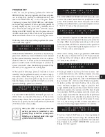
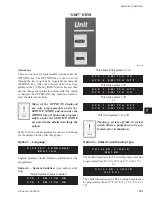
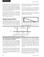
Programming of the cooling setpoints, daily schedule,
and safeties is accomplished by using the keys located
under the SETPOINTS section.
The three keys involved are labeled COOLING
SETPOINTS, SCHEDULE/ADVANCE DAY, and
PROGRAM.
Following are instructions for programming the
respective setpoints. The same instruction should be
used to view the setpoints with the exception that the
setpoint will not be changed.
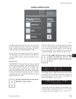
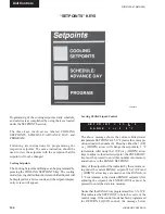
Cooling Setpoints
The Cooling Setpoint and Range can be programmed by
pressing the COOLING SETPOINTS key. The cooling
mode (leaving chilled liquid or return chilled liquid) will
be displayed for a few seconds, and the setpoint display
entry screen will appear.
“SETPOINTS” KEYS
00069VIP
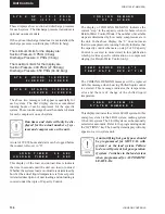
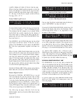
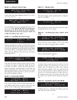
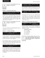
Leaving Chilled Liquid Control
The above message shows the current chilled water
temperature SETPOINT at 45.0 °F (notice the cursor po-
sitioned under the number 0). Pressing either the
↑
(UP)
or
↓
(DOWN) arrow will change the setpoint in .5 °F
increments. After using the
↑
(UP) or
↓
(DOWN) arrow
keys to adjust to the desired setpoint, the ENTER/ADV
key must be pressed to enter this number into memory
and advance to the RANGE SETPOINT.
Entry of the setpoint will be indicated by the cursor mov-
ing under the current RANGE setpoint. The
↑
(UP) and
↓
(DOWN) arrow keys are used to set the RANGE, in
.5 °F increments, to the desired RANGE setpoint. After
adjusting the setpoint, the ENTER/ADV key must be
pressed to enter the data into memory.
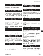
Notice that the RANGE was programmed for
+/-
X.X° F.
This indicates the SETPOINT to be in the
center
of the
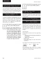
control range. If the control mode has been programmed
for RETURN LIQUID control, the message below
S E T P O I N T = 4 5 . 0 ° F
R A N G E = +/- 2 . 0 ° F
Содержание YCAL0019
Страница 55: ...FORM 150 67 NM2 209 55 JOHNSON CONTROLS 5 5 ELEMENTARY WIRING DIAGRAM CON T LD12699D...
Страница 57: ...FORM 150 67 NM2 209 57 JOHNSON CONTROLS 5 5 ELEMENTARY WIRING DIAGRAM CON T LD12693C...
Страница 59: ...FORM 150 67 NM2 209 59 JOHNSON CONTROLS 5 5 ELEMENTARY WIRING DIAGRAM CON T LD 12198...
Страница 61: ...FORM 150 67 NM2 209 61 JOHNSON CONTROLS 5 5 LD12702 ELEMENTARY WIRING DIAGRAM CON T...
Страница 63: ...FORM 150 67 NM2 209 63 JOHNSON CONTROLS 5 5 LD12696 ELEMENTARY WIRING DIAGRAM CON T...
Страница 65: ...FORM 150 67 NM2 209 65 JOHNSON CONTROLS 5 5 CONNECTION WIRING DIAGRAM CON T LD12703B...
Страница 67: ...FORM 150 67 NM2 209 67 JOHNSON CONTROLS 5 5 CONNECTION WIRING DIAGRAM CON T LD12697B...