

FORM 150.67-NM2 (209)
181
JOHNSON CONTROLS
9
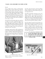
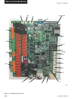
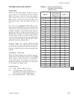
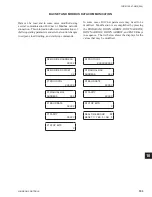
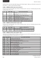
CHECKING INPUTS AND OUTPUTS
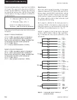
Digital Inputs
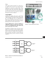
Refer to the unit wiring diagram. All digital inputs are
connected to J13-1 of the I/O board. The term “digital”
refers to two states – either on or off. As an example,
when the
fl
ow switch is closed, 30 volts
DC
will be
applied to J13, pin 5 (J13-5) of the I/O board. If the
fl
ow switch is open, 0 volts DC will then be present at
J13-5.
Pin 1 of J13 is an
unregulated
30VDC
source
used to
supply the DC voltage to the various user contacts, unit
switch,
fl
ow switch, etc. This DC source is factory wired
to CTB1, terminal 13. Any switch or contact used as a
digital input would be connected to this terminal, with
the other end connecting to its respective digital input on
the microboard. Any time a switch or contact is closed,
30VDC would be applied to that particular digital input.
Any time a switch or contact is open, 0VDC would be
applied to that particular digital input.
Typically, voltages of 24 – 36VDC could be measured
for the DC voltage on the digital inputs. This voltage
is in reference to ground. The unit case should be suf-
fi
cient as a reference point when measuring digital input
voltages.
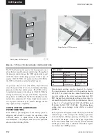
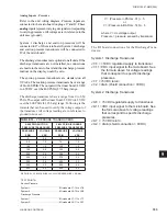
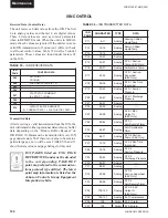
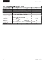
Analog Inputs – Temperature
Refer to the unit wiring diagram. Temperature inputs are
connected to the microboard on plug J6. These
analog
inputs represent varying DC signals corresponding to
varying temperatures. All voltages are in reference to
the unit case (ground). Following are the connections
for the temperature sensing inputs:
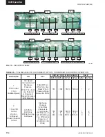
Outside Air Sensor
J6-6 = +5VDC regulated supply to sensor.
J6-9 = VDC input signal to the microboard.
See Table 29 for voltage readings that corre
spond to speci
fi
c outdoor temperatures.
J6-3 = drain (shield connection = 0VDC) Return
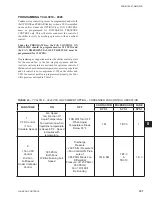
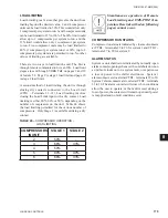
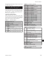
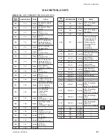
TABLE 31 –
OUTDOOR AIR SENSOR
TEMPERATURE/VOLTAGE/
CORRELATION
TEMP °F
VOLTAGE
(Signal Input
to Return)
TEMP °C
0
0.7
-18
5
0.8
-15
10
0.9
-12
15
1.0
-9
20
1.1
-7
25
1.2
-4
30
1.4
-1
35
1.5
2
40
1.7
4
45
1.8
7
50
2.0
10
55
2.2
13
60
2.3
16
65
2.5
18
70
2.6
21
75
2.8
24
80
2.9
27
85
3.1
29
90
3.2
32
95
3.4
35
100
3.5
38
105
3.6
41
110
3.7
43
115
3.8
46
120
3.9
49
125
4.0
52
130
4.1
54
Содержание YCAL0019
Страница 55: ...FORM 150 67 NM2 209 55 JOHNSON CONTROLS 5 5 ELEMENTARY WIRING DIAGRAM CON T LD12699D...
Страница 57: ...FORM 150 67 NM2 209 57 JOHNSON CONTROLS 5 5 ELEMENTARY WIRING DIAGRAM CON T LD12693C...
Страница 59: ...FORM 150 67 NM2 209 59 JOHNSON CONTROLS 5 5 ELEMENTARY WIRING DIAGRAM CON T LD 12198...
Страница 61: ...FORM 150 67 NM2 209 61 JOHNSON CONTROLS 5 5 LD12702 ELEMENTARY WIRING DIAGRAM CON T...
Страница 63: ...FORM 150 67 NM2 209 63 JOHNSON CONTROLS 5 5 LD12696 ELEMENTARY WIRING DIAGRAM CON T...
Страница 65: ...FORM 150 67 NM2 209 65 JOHNSON CONTROLS 5 5 CONNECTION WIRING DIAGRAM CON T LD12703B...
Страница 67: ...FORM 150 67 NM2 209 67 JOHNSON CONTROLS 5 5 CONNECTION WIRING DIAGRAM CON T LD12697B...