
JOHNSON CONTROLS
36
FORM 150.67-NM2 (209)
Installation
DUCT WORK CONNECTION
General Requirements
The following duct work recommendations are
intended to ensure satisfactory operation of the unit.
Failure to follow these recommendations could cause
damage to the unit, or loss of performance, and may
invalidate the warranty.
When ducting is to be
fi
tted to the fan discharge it
is recommended that the duct should be the same
cross-sectional area as the fan outlet and straight for
at least three feet (1 meter) to obtain static regain
from the fan. Duct work should be suspended with
fl
exible hangers to prevent noise and vibration being
transmitted to the structure. A
fl
exible joint is also
recommended between the duct attached to the fan
and the next section for the same reason. Flexible
connectors should not be allowed to concertina.
The unit(s) is not designed to take structural loading.
No signi
fi
cant amount of weight should be allowed
to rest on the fan outlet
fl
ange, deck assemblies or
condenser coil module. No more than 3 feet (1 meter)
of light construction duct work should be supported
by the unit. Where cross winds may occur, any duct
work must be supported to prevent side loading on the
unit.
If the ducts from two or more fans are to be combined
into a common duct, back-
fl
ow dampers should be
fi
tted in the individual fan ducts. This will prevent re-
circulation of air when only one of the fans is running.
Units are supplied with outlet guards for safety and
to prevent damage to the fan blades. If these guards
are removed to
fi
t duct work, adequate alternative
precautions must be taken to ensure persons cannot be
harmed or put at risk from rotating fan blades.
WIRING
Liquid Chillers are shipped with all factory-mounted
controls wired for operation.
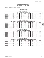
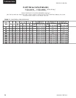
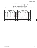
Field Wiring –
Power wiring must be provided through
a fused disconnect switch to the unit terminals (or
optional molded disconnect switch) in accordance with
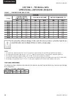
N.E.C. or local code requirements. Minimum circuit
ampacity and maximum dual element fuse size are
given in Tables 6.
Copper power wiring only should be used for supplying
power to the chiller. This is recommended to avoid safety
and reliability issues resulting from connection failure at
the power connections to the chiller. Aluminum wiring
is not recommended due to thermal characteristics
that may cause loose terminations resulting from the
contraction and expansion of the wiring. Aluminum
oxide may also build up at the termination causing hot
spots and eventual failure. If aluminum wiring is used
to supply power to the chiller, AL-CU compression
fi
ttings should be used to transition from aluminum to
copper. This transition should be done in an external
box separate to the power panel. Copper conductors
can then be run from the box to the chiller.
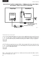
A 120-1-60, 15 amp source must be supplied for the
control panel through a fused disconnect when a control
panel transformer (optional) is not provided (Refer to
FIG. 8).
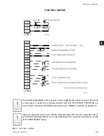
See unit wiring diagrams for
fi
eld and power wiring
connections, chilled water pump starter contacts,
alarm contacts, compressor run status contacts, PWM
input, and load limit input. Refer to section on UNIT
OPERATION for a detailed description of operation
concerning aforementioned contacts and inputs.
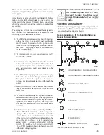
Evaporator Pump Start Contacts
Terminal block TB1 – terminals 23 to 24, are nor mally-
open contacts that can be used to switch
fi
eld supplied
power to provide a start signal to the evapo rator pump
contactor. The contacts will be closed when any of the
following conditions occur:
1. Low Leaving Chilled Liquid Fault
2. Any compressor is running
3. Daily schedule is not programmed OFF and the
Unit Switch is ON
The pump will not run if the micro panel has been
powered up for less than 30 seconds, or if the pump
has run in the last 30 seconds, to prevent pump motor
overheating. Refer to FIG. 9 and unit wiring dia gram.
System Run Contacts
Contacts are available to monitor system status.
Normally-open auxiliary contacts from each com pressor
contactor are wired in parallel with TB1 – terminals 25
to 26 for system 1, and TB1 – termi nals 27 to 28 for
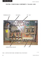
system 2 (YCAL0043 - YCAL0066). Refer to FIG. 4,
9 and unit wiring diagram.
Содержание YCAL0019
Страница 55: ...FORM 150 67 NM2 209 55 JOHNSON CONTROLS 5 5 ELEMENTARY WIRING DIAGRAM CON T LD12699D...
Страница 57: ...FORM 150 67 NM2 209 57 JOHNSON CONTROLS 5 5 ELEMENTARY WIRING DIAGRAM CON T LD12693C...
Страница 59: ...FORM 150 67 NM2 209 59 JOHNSON CONTROLS 5 5 ELEMENTARY WIRING DIAGRAM CON T LD 12198...
Страница 61: ...FORM 150 67 NM2 209 61 JOHNSON CONTROLS 5 5 LD12702 ELEMENTARY WIRING DIAGRAM CON T...
Страница 63: ...FORM 150 67 NM2 209 63 JOHNSON CONTROLS 5 5 LD12696 ELEMENTARY WIRING DIAGRAM CON T...
Страница 65: ...FORM 150 67 NM2 209 65 JOHNSON CONTROLS 5 5 CONNECTION WIRING DIAGRAM CON T LD12703B...
Страница 67: ...FORM 150 67 NM2 209 67 JOHNSON CONTROLS 5 5 CONNECTION WIRING DIAGRAM CON T LD12697B...