
JOHNSON CONTROLS
190
FORM 150.67-NM2 (209)
Maintenance
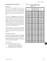
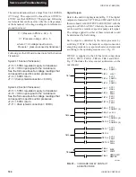
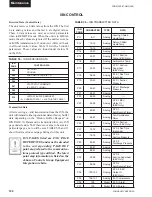
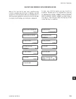
Received Data (Control Data)
The unit receives 8 data values from the ISN. The
fi
rst
4 are analog values and the last 4 are digital values.
These 8 data values are used as control parameters
when in REMOTE mode. When the unit is in LOCAL
mode, these 8 values are ignored. If the unit receives no
valid ISN transmission for 5 minutes it will revert back
to all local control values. Table 35 lists the 5 control
parameters. These values are found under feature 54
on the ISN.
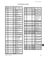
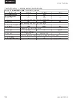
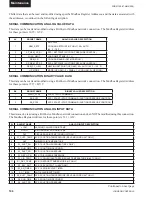
ISN CONTROL
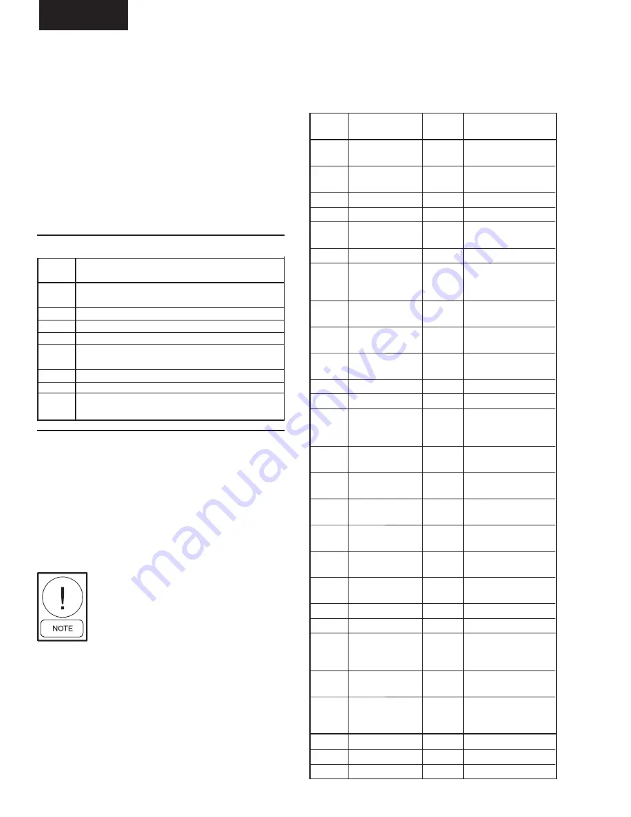
TABLE 36 –
ISN TRANSMITTED DATA
ISN
PAGE
CHARACTER
TYPE
DATA
P11
8-11
Analog
Leaving Chilled
Liquid Temp.
P12
12-15
Analog
Return Chilled
Liquid Temp.
P13
16-19
Analog
----
P14
20-23
Analog
----
P15
24-27
Analog
SYS 1 Suction
Temp. (EEV Only)
P16
28-31
Analog
Ambient Air Temp.
P17
32-35
Analog
SYS 1 Suction
Superheat
(EEV Only)
P18
36-39
Analog
SYS 1 Run Time
(Seconds)
P19
40-43
Analog
SYS 1 Suction
Pressure
P20
44-47
Analog
SYS 1 Discharge
Pressure
P21
48-51
Analog
----
P22
52-55
Analog
----
P23
56-59
Analog
SYS 1 EEV
Output %
(EEV Only)
P24
60-63
Analog
SYS 1
Anti-Recycle Timer
P25
64-67
Analog
Anti-Coincidence
Timer
P26
68-71
Analog
SYS 2 Suction
Temp. (EEV Only)
P27
72-75
Analog
SYS 2 Run Time
(Seconds)
P28
76-79
Analog
SYS 2
Suction Pressure
P29
80-83
Analog
SYS 2
Discharge Pressure
P30
84-87
Analog
----
P31
88-91
Analog
----
P32
92-95
Analog
SYS 2
Suction Superheat
(EEV Only)
P33
96-99
Analog
SYS 2
Anti-Recycle Timer
P34
100-103
Analog
SYS 2 EEV
Output %
(EEV Only)
P35
104-107
Analog
# of Compressors
P36
108
Digital
SYS 1 Alarm
P37
109
Digital
SYS 2 Alarm
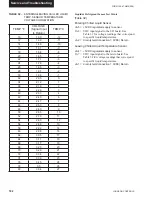
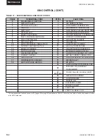
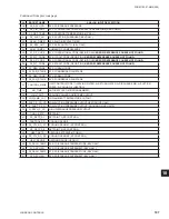
Transmitted Data
After receiving a valid transmission from the ISN, the
unit will transmit either operational data or history buffer
data depending on the “History Buffer Request” on
ISN PAGE 10. Data must be transmitted for every ISN
page under feature 54. If there is no value to be sent to a
particular page, a zero will be sent. TABLES 36 and 37
show the data values and page listings for this unit.
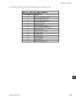
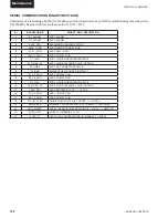
ISN PAGES listed are ENG PAGE
REFERENCES and must be decoded
to the corresponding PAGE REF
point map related to the communica-
tions protocol type utilized. The latest
point map information is listed on the
Johnson Controls Group Equipment
Integration website.
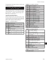
TABLE 35 –
ISN RECEIVED DATA
ISN
CONTROL DATA
PAGE
P03
SETPOINT
COOLING
P04
LOAD LIMIT STAGE (0,1, 2)
P05
–
P06
–
P07
START/STOP
COMMAND
(0 = STOP, 1 = RUN)
P08
—
P09
—
P10
HISTORY BUFFER REQUEST
(0 = CURRENT DATA, 1 = LAST HISTORY DATA)
Содержание YCAL0019
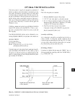
Страница 55: ...FORM 150 67 NM2 209 55 JOHNSON CONTROLS 5 5 ELEMENTARY WIRING DIAGRAM CON T LD12699D...
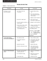
Страница 57: ...FORM 150 67 NM2 209 57 JOHNSON CONTROLS 5 5 ELEMENTARY WIRING DIAGRAM CON T LD12693C...
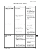
Страница 59: ...FORM 150 67 NM2 209 59 JOHNSON CONTROLS 5 5 ELEMENTARY WIRING DIAGRAM CON T LD 12198...
Страница 61: ...FORM 150 67 NM2 209 61 JOHNSON CONTROLS 5 5 LD12702 ELEMENTARY WIRING DIAGRAM CON T...
Страница 63: ...FORM 150 67 NM2 209 63 JOHNSON CONTROLS 5 5 LD12696 ELEMENTARY WIRING DIAGRAM CON T...
Страница 65: ...FORM 150 67 NM2 209 65 JOHNSON CONTROLS 5 5 CONNECTION WIRING DIAGRAM CON T LD12703B...
Страница 67: ...FORM 150 67 NM2 209 67 JOHNSON CONTROLS 5 5 CONNECTION WIRING DIAGRAM CON T LD12697B...