17-5
IM AQ1200-01EN
Event Mapper
3
2
1
4
5
6
7
8
9
10
11
12
13
14
15
16
17
18
19
App
Index
20
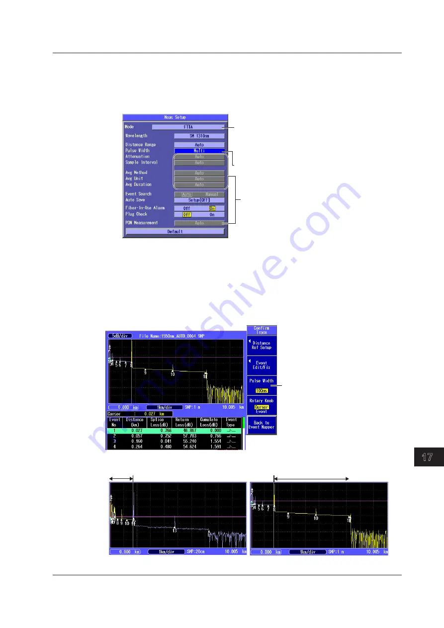
• Setting the Measurement Mode and Pulse Width
4.
Press
SETUP
and then the
Meas Setup
soft key. The following screen appears.
5.
Using the
rotary knob
and
ENTER
, set the mode to FTTA.
6.
Using the
rotary knob
and
ENTER
, set the pulse width to multi pulse width.
Setting the Measurement Mode
(Simple, Detail, Multi WL, FTTA)
The Multi WL option is not available on
the AQ1200B and AQ1200C.
Pulse width (Auto, Multi)
In FTTA mode, these are fixed to Auto.
Setting Analysis Conditions and Executing Measurements (See page 17-2)
The procedure is the same as that in Detail mode (except the Current Trace soft key is not
displayed on the OTDR menu when executing measurements). During measurement, averaged
measurement of multiple pulse widths is continuously executed.
Waveform Confirmation Screen
The waveforms measured using multiple pulse widths can be displayed alternately on the screen.
Press the Confirm Trace soft key. The following screen appears.
Select the pulse width.
You can select to display the waveform
measured at each pulse width. In the
screen example, the pulse width is
automatically set to 10 ns for the near-end
side and 100 ns for the far-end side.
Waveform of 10 ns pulse width
Near-end side
Waveform of auto pulse width (100 ns)
Far-end side
The boundary between near end and far end is set automatically. You cannot move the boundary.
The yellow portion is the waveform display of the near-end side or far-end side.
17.1 Displaying Optical Fiber Events as Icons


