


Protective and Diagnostic Functions
7-
5
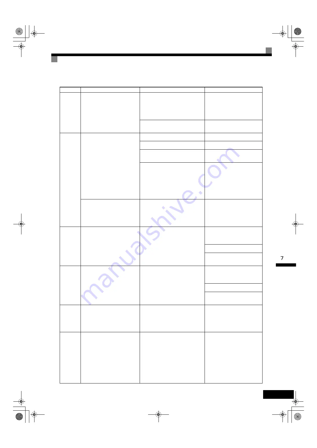
LF
Output Pha
Loss
Output Open-phase
An open-phase occurred at the
Inverter output.
This fault is detected when L8-07 is
set to 1 or 2
• There is a broken wire in the output
cable.
• There is a broken wire in the motor-
winding.
• The output terminals are loose.
Reset the fault after correcting its
cause.
The motor being used has a capacity
less than 5% of the rated output current.
Check the motor and Inverter
capacity.
OH
(OH1)
Heatsnk
Overtemp
(Heatsnk
MAX
Temp)
Cooling Fin Overheating
The temperature of the Inverter's
cooling fins exceeded the setting in
L8-02 or the overheat protection
level.
OH: The temperature exceeded the
setting in L8-02 (Stopping method
can be changed by L8-03.).
OH1: The temperature exceeded
100
°
C (Stopping method: Coast to
stop).
The ambient temperature is too high.
Install a cooling unit.
There is a heat source nearby.
Remove the heat source.
The Inverter's cooling fan has stopped.
Replace the cooling fan. (Contact
our sales representative.)
• A short-circuit bV,
−
V, and
AC terminals occurred.
• Overload in the control circuit termi-
nal.
• Make sure that incorrect wiring
has not been done.
• Check the resistance and wiring
for the frequency setting potenti-
ometer, etc. (Check that the cur-
rent for terV and –V is
20 mA or less.)
Inverter's Cooling Fan Fault
(200 V Class: 7.5 kW or more,
400 V Class: 5.5 kW or more)
This fault is detected when L8-32 is
set to 1.
• The Inverter's cooling fan has
stopped.
• The heatsink is clogged.
• Replace the cooling fan. (Con-
tact our sales representative.)
• Clean the heatsink.
OH3
Motor
Overheat 1
Motor Overheating Alarm
The Inverter will stop or will con-
tinue to operate according to the
setting of L1-03.
The motor has overheated.
Check the size of the load and the
length of the acceleration, deceler-
ation, and cycle times.
Check the V/f characteristics.
Check the Motor Rated Current
(E2-01).
OH4
Motor
Overheat 2
Motor Overheating Fault
The Inverter will stop according to
the setting of L1-04.
The motor has overheated.
Check the size of the load and the
length of the acceleration, deceler-
ation, and cycle times.
Check the V/f characteristics.
Check the Motor Rated Current
(E2-01).
RH
DynBrk
Resistor
Installed Braking Resistor Over-
heating
Braking resistor protection func-
tion set in L8-01 has operated.
The deceleration time is too short and
the regenerative energy from the motor
is too large.
• Reduce the load, increase the
deceleration time, or reduce the
motor speed.
• Change to a Braking Resistor
Unit.
RR
DynBrk
Transistr
Internal Braking Transistor Fault
The braking transistor is not operat-
ing properly.
• The braking transistor is damaged.
• The Inverter’s control circuits are
faulty.
• Disconnect the Braking Resis-
tor wiring, turn ON the power
supply again, and operate the
motor. If the power supply is
turned ON while the Braking
Resistor wiring is connected, the
Braking Resistor or Inverter
may overheat and be damaged.
• Replace the Inverter if the fault
continues to occur.
Table 7.1 Fault Displays and Processing (Continued)
Display
Meaning
Probable Causes
Corrective Actions
TOE-S616-60.1.book 5 ページ 2017年8月4日 金曜日 午後3時41分